
Installation Guide
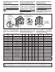
MODEL
MODÈLE
MODELO
No A B C D E
Overflow height
Hauteur trop-plein
Altura del rebosadero
Installation Type
Type d’installation
Tipo de la instalación
Allia TSR-6032
1-piece with roof / Monocoque avec toît
107000
60 1/8
(1527)
30 1/2
(775)
87
(2210)
15 1/2
(394)
8 1/2
(216)
16 7/8
(429)
Fig. 17.1 , Fig. 21.2a
Allia TS-6032
1-piece without roof / Monocoque sans toît
107001
60 1/8
(1527)
31 1/2
(800)
80
(2032)
16 1/2
(419)
8 1/2
(216)
16 7/8
(429)
Fig. 17.1 , Fig. 21.1
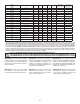
Allia TSR-6032
1-piece with roof / Monocoque avec toît
with massage system / avec système de massage
107000
with massage system / avec système de massage
60 1/8
(1527)
32
(813)
87
(2210)
17
(432)
8 1/2
(216)
16 7/8
(429)
Fig. 17.1 , Fig. 17.1.1 , Fig.
21.2a,
Allia TS-6032
1-piece without roof / Monocoque sans toît
with massage system / avec système de massage
107001
with massage system / avec système de massage
60 1/8
(1527)
32
(813)
80
(2032)
17
(432)
8 1/2
(216)
16 7/8
(429)
Fig. 17.1 , Fig. 17.1.1 , Fig.
21.1,
Allia SHR-6034
1-piece with roof / Monocoque avec toît
Right drain / Drain droit / Desagüe a la derecha
107002
60 1/8
(1527)
32 1/4
(819)
87
(2210)
16 1/4
(413)
8 1/2
(216)
- Fig. 17.1 , Fig. 21.2a
Allia SHR-6034
1-piece with roof / Monocoque avec toît
with central drain / avec drain central
107002
60 1/8
(1527)
32 1/4
(819)
87
(2210)
16 1/4
(413)
30
(762)
- Fig. 17.1 , Fig. 21.2a
Allia SH-6034
1-piece without roof / Monocoque sans toît
Right drain / Drain droit / Desagüe a la derecha
107003
60 1/8
(1527)
33
(838)
80
(2032)
17
(432)
8 1/2
(216)
- Fig. 17.1 , Fig. 21.1
Allia SH-6034
1-piece without roof / Monocoque sans toît
with central drain / avec drain central
107003
60 1/8
(1527)
33
(838)
80
(2032)
17
(432)
30
(762)
- Fig. 17.1 , Fig. 21.1
Allia SHR-4834
1-piece with roof / Monocoque avec toît
107004
48 1/8
(1222)
32 1/4
(819)
87
(2210)
16 1/4
(413)
24
(610)
- Fig. 17.1 , Fig. 21.2a
Allia SH-4834
1-piece without roof / Monocoque sans toît
107005
48 1/8
(1222)
33
(838)
80
(2032)
17
(432)
24
(610)
- Fig. 17.1 , Fig. 21.1
Allia SHR-3636
1-piece with roof / Monocoque avec toît
107006
36 1/8
(918)
34 1/4
(870)
87
(2210)
17 1/4
(438)
18
(457)
- Fig. 17.1 , Fig. 21.2a
Allia SH-3636
1-piece without roof / Monocoque sans toît
107007
36 1/8
(918)
35
(889)
80
(2032)
18
(457)
18
(457)
- Fig. 17.1 , Fig. 21.1
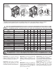
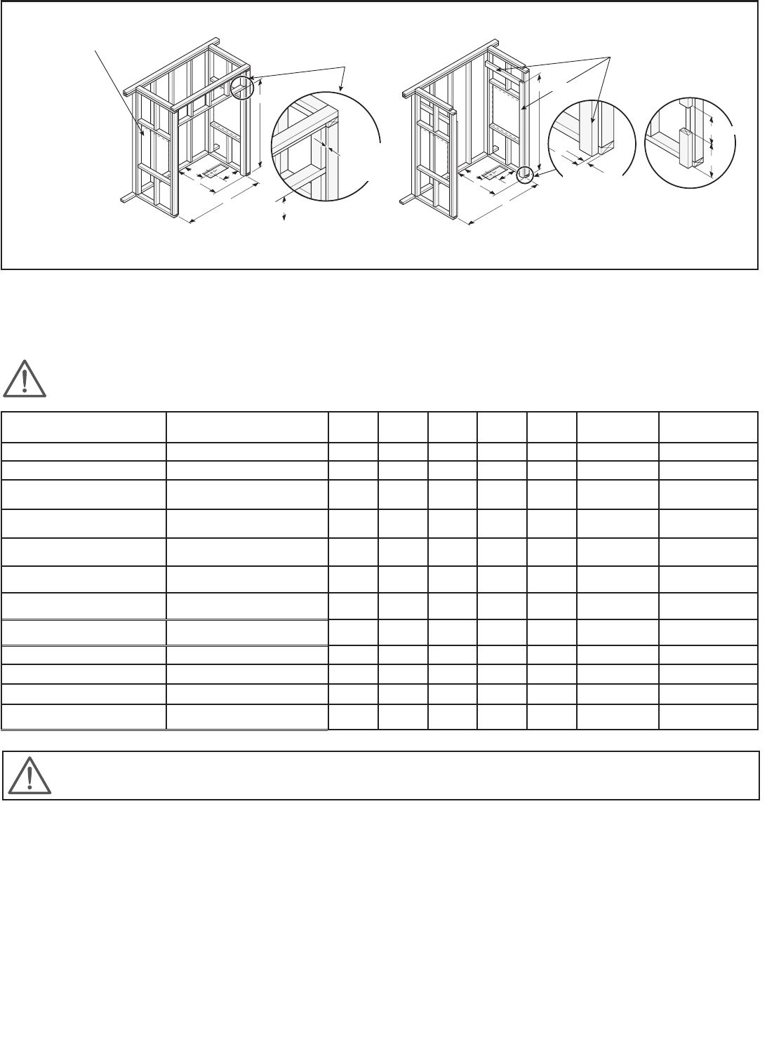
A
B
D
E
C
(ABFLR)
Allow an accessway
to the faucet
Prévoir une trappe d’accès
pour la robinetterie
Prever una trampilla de
acceso para la griferia
Additional stud for roofcap
Partie supplémentaire pour toit
Parte suplementaria para el techo
Recessed 3/8”
Encastré 3/8”
Empotrado 3/8”
(9.5mm)
A
E
Recessed 3/8”
Encastré 3/8”
Empotrado 3/8”
(9.5mm)
Additional studs for flange
Partie supplémentaire pour bride
Parte suplementaria para la brida
12”(305mm)
16”(406mm) ABFLR (standard)
*
*
C
(ABFLR)
B
B
D
C
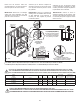
Fig. 17.1
Fig. 17.1.1
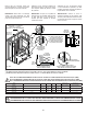
For all Allia models the
alcove must have 2 frontal 2” x 4” studs
installed to fasten the tile flange. They
have to be recessed by 3/8” (Fig. 17.1).
When there is a massage
system with Allia TSR-6032 and Allia
TS-6032 the stud must be cut (Fig. 17.1.1)
to be able to push the unit into the alcove.
Pour tous les modèles Allia
l’alcôve doit avoir 2 montants 2” x 4”
installés en façade afin de fixer la bride
de carrelage. Ils sont décalés de 3/8” (Fig.
17.1).
Lorsqu’il y a un système de
massage avec les modèles Allia TS-6032
et Allia TSR-6032 il faut découper le
montant (Fig. 17.1.1) pour être capable de
pousser l’unité dans l’alcôve.
Para todos los modelos
Allia el nicho debe tener 2 montantes
2” x 4” frontales instalados para atornillar la
brida de sujeción. Estos montantes tienen
que venir empotrados 3/8” (Fig. 17.1).
Cuando se tiene un
sistema de masaje con los modelos
Allia TS-6032 y Allia TSR-6032 se debe
recortar el montante (Fig. 17.1.1) para
poder empujar la unidad dentro del nicho.
23
NOTE: THE FOLLOWING MEASUREMENTS ARE NOT THOSE OF THE UNIT BUT THOSE REQUIRED FOR INSTALLATION (±1/4” (6MM)).
NOTE: LES DIMENSIONS CI-DESSOUS NE SONT PAS CELLES DE L’UNITÉ, MAIS CELLES REQUISES POUR L’INSTALLATION (±1/4” (6MM)).
NOTA: LAS DIMENSIONES INDICADAS A CONTINUACIÓN NO SON LAS DE LA UNIDAD, SINO LAS REQUERIDAS PARA LA INSTALACIÓN (±1/4” (6MM)).
STRUCTURE MEASUREMENTS MUST BE VERIFIED AGAINST THE UNIT
LES DIMENSIONS DE LA STRUCTURE DOIVENT ÊTRE VÉRIFIÉES À PARTIR DES DIMENSIONS DE L’UNITÉ
LAS DIMENSIONES DE LA ESTRUCTURA DEBEN SER VERIFICADAS A PARTIR DE LAS DIMENSIONES DE LA UNIDAD
*
Optional not ABFLR available only on 107000 and 107001, remove 2” to the ABFLR measurement to obtain not ABFLR.
*
Non ABFLR optionnel disponible seulement pour 107000 et 107001, enlever 2” de la mesure ABFLR pour obtenir non ABFLR
.
*
No ABFLR opcional disponible solamente en 107000 y 107001, restar 2” a la medida ABFLR para obtener no ABFLR.