COREINK 2020 V0.
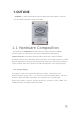
1. OUTLINE COREINK is ESP32 board which based on ESP32-PICO-D4 module, contained 1.54-inch eINK. The board is made of PC+ABC. 1.1 Hardware Composition The hardware of COREINK: ESP32-PICO-D4 chip, eLNK, LED, Button, GROVE interface, TypeC-to-USB interface, RTC,Power Management chip battery. ESP32- PICO-D4 is a System-in-Package (SiP) module that is based on ESP32, providing complete Wi-Fi and Bluetooth functionalities. The module integrates a 4-MB SPI flash.
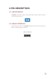
2. PIN DESCRIPTION 2.1. USB INTERFACE COREINK Configuration Type-C type USB interface, support USB2.0 standard communication protocol. 2.2. GROVE INTERFACE 4p disposed pitch of 2.0mm COREINK GROVE interfaces, internal wiring and GND, 5V, GPIO4, GPIO13 connected.
3. FUNCTIONAL DESCRIPTION This chapter describes the ESP32-PICO-D4 various modules and functions. 3.1. CPU AND MEMORY ESP32-PICO-D4 contains two low-power Xtensa ® 32-bit LX6 MCU.
3.3. CRYSTAL • ESP32-PICO-D4 integrates a 40 MHz crystal oscillator. 3.4. RTC MANAGEMENT AND LOW POWER CONSUMPTION ESP32 uses advanced power management techniques may be switched between different power saving modes. (See Table 5). • Power saving mode - Active Mode: RF chip is operating. Chip may receive and transmit a sounding signal. - Modem-sleep mode: CPU can run, the clock may be configured. Wi-Fi / Bluetooth baseband and RF - Light-sleep mode: CPU suspended.
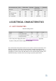
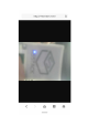
4. ELECTRICAL CHARACTERISTICS 4.1. LIMIT PARAMETERS Table 8: Limiting values 1. VIO to the power supply pad, Refer ESP32 Technical Specification Appendix IO_MUX, as SD_CLK of Power supply for VDD_SDIO. Press and hold the side power button for two seconds to start the device.Press and hold for more than 6 seconds to turn off the device. Switch to the photo mode through the Home screen, and the avatar that can be obtained through the camera is displayed on the tft screen.
FCC Statement Any Changes or modifications not expressly approved by the party responsible for compliance could void the user’s authority to operate the equipment. This device complies with part 15 of the FCC Rules. Operation is subject to the following two conditions: (1) This device may not cause harmful interference,and (2) This device must accept any interference received, including interference that may cause undesired operation.
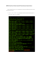
ESP32TimerCam/TimerCameraF/TimerCameraX Quick Start With preloaded firmware, your ESP32TimerCam,/TimerCameraF/TimerCameraX would run right after power on. 1. Power on the cable into ESP32TimerCam/TimerCameraF/TimerCameraX by USB cable. Baud rate 921600.
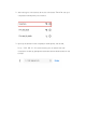
2. After waitting for a few seconds, Wi-Fi scan a AP named "TimerCam" with your computer(or mobile phone), and connect it. 3. Open up the browser on the computer(or mobile phone), visit the URL http://192.168.4.1:81. At the moment, your can see the real-time transmission of video by ESP32TimerCam/TimerCameraF/TimerCameraX on the browser.
A Bluetooth name "m5stack" is found on the mobile phone_ BLE”