
user manual


FFD 3.5" SCSI Flash Disk User Manual
45-SR-001-01-7L REV 4.0 14 of 22
7 LED Indicators and Configuration Switch
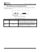
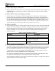
Figure 4 illustrates the two LEDs located on the FFD front panel. Table 6 Describes the LED color
codes and status definitions.
Figure 4: Front Panel LED Indicators
Table 6: LED Status Description
Status LED Color Indicator Description
POWER Green Indicates that power is applied to the disk. The LED
remains ON if everything is okay, and flashes at a rate
of 1 Hz to indicate that the power-up and built-in self
test have failed and that the disk is malfunctioning.
BUSY Red Indicates that the FFD is being accessed. The LED is lit
when the disk is accessed (read/write/format) and
remains lit until the access is completed.