FFD 2.5" and 3.5" IDE Plus Flash Disk User Manual January 2004 48-SR-003-03-7L Rev 2.
DOCUMENT CONTROL INFORMATION DCO No.: N/A 2 Title Name Date Issued by: Assistant Vice President, Rugged Market Ofer Tsur October 12, 2003 Updated by: DiskOnChip Rugged Product Manager Pnina Sharir January 7, 2004 FFD 2.5" and 3.5" IDE Plus Flash Disk User Manual 48-SR-003-03-7L Rev 2.
TABLE OF CONTENTS 1 General................................................................................................................................... 4 2 Kit Contents........................................................................................................................... 4 3 Visual Inspection................................................................................................................... 4 4 Handling Instructions ...........................................
1 GENERAL This manual provides you with the information you need to properly install your new FFD 2.5” or 3.5” IDE Plus Flash Disk. M-Systems recommends that qualified and trained personnel install the drive. The following chapters contain handling information, mounting considerations, address and configuration setups, cabling and connector information and information about obtaining technical assistance and service.
4 HANDLING INSTRUCTIONS You can prolong the life of your IDE Plus, increase its reliability and prevent unnecessary damage by following the instructions listed below. Failure to follow any of these instructions may void your warranty. • Always take all proper electrostatic discharge (ESD) precautions, including personnel and equipment grounding. • Always operate the IDE Plus within the environmental specifications. • Always use a grounded wrist strap when handling the IDE Plus.
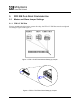
5 FFD IDE PLUS DRIVE CONFIGURATION 5.1 Master and Slave Jumper Settings 5.1.1 FFD 2.5” IDE Plus Prior to mounting the drive in the system drive bay, the FFD 2.5” IDE Plus must be configured according to Figure 1and Figure 2. Figure 1: FFD 2.5" IDE Plus Address Setting by Jumper Figure 2: FFD 2.5" IDE Plus Slave Setting by Jumper 6 FFD 2.5" and 3.5" IDE Plus Flash Disk User Manual 48-SR-003-03-7L Rev 2.
5.1.2 FFD 3.5” IDE Plus Prior to mounting the drive in the system drive bay, the FFD 3.5” IDE Plus must be configured according to Figure 3. Figure 3: FFD 3.5" IDE Plus Jumper Settings 7 FFD 2.5" and 3.5" IDE Plus Flash Disk User Manual 48-SR-003-03-7L Rev 2.
5.2 Write-Protect Jumper Settings The FFD IDE Plus has a write-protect option that is controlled by the jumper settings. 5.2.1 FFD 2.5” IDE Plus Figure 4 illustrates the jumper configuration for the write-protect option for the FFD 2.5” IDE Plus. Figure 4: FFD 2.5" IDE Plus Write Protect Jumper Settings 8 FFD 2.5" and 3.5" IDE Plus Flash Disk User Manual 48-SR-003-03-7L Rev 2.
5.2.2 FFD 3.5” IDE Plus Figure 5: illustrates the jumper configuration for the write-protect option for the FFD 3.5” IDE Plus. Figure 5: FFD3.5” IDE Plus Write Protect Jumper Settings 9 FFD 2.5" and 3.5" IDE Plus Flash Disk User Manual 48-SR-003-03-7L Rev 2.
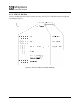
5.3 Interface Connectors 5.3.1 FFD 2.5” IDE Plus The FFD 2.5” IDE Plus has a 2.00 mm pitch interface connector located on the rear panel. The DC power and IDE bus are input through a non-shielded 50-pin flat cable. Figure 6: FFD 2.5” IDE Plus Interface Connector It is recommended that the mating connector be blocked at pin 27 using a special plastic key (the key can be ordered from the connector manufacturer). This prevents possible damage to the disk by connecting the cable with a 180º rotation. 5.3.
6 INSTALLATION 6.1 System Requirements In order to install the IDE Plus in your system, ensure that you have the following items: • System mounting hardware • 44-pin ribbon IDE cable for FFD 2.5” IDE Plus, or 40-pin cable for FFD 3.5” IDE Plus 6.2 FFD IDE Plus Configuration Before mounting the drive into the system drive bay, you must first configure the IDE Plus by setting the address jumper to comply with your system requirements. See Section 5 for details. 6.
1. Run the DOS FDISK program to partition the IDE Plus. 2. Run the DOS FORMAT command to high-level format the IDE Plus. 3. If you want the IDE Plus to be a bootable drive, run the DOS SYS command and change its partition to active. 12 FFD 2.5" and 3.5" IDE Plus Flash Disk User Manual 48-SR-003-03-7L Rev 2.
7 DRIVE PARAMETERS Most IDE device drivers can automatically detect the total number of sectors in the IDE Plus, using the IDENTIFY DRIVE command, and configure them accordingly. However, some older device drivers need to obtain the drive geometry parameters manually. The physical drive parameters are just a convention and have no effect on the way data is stored within the IDE Plus.
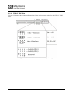
Number of Number of Unformatted Total Number of Number of Current CHS Disk Capacity User-Addressable Logical Sectors Logical Heads Logical Cylinders Capacity (Words 3 and 55 (Words 1 and 54 after per Track (MB) Sectors in LBA (Sectors) after power-on of power-on) of IDENTIFY (Words 57/58 after (Words 6 and 56 Mode 14 (Words 60/61 of IDENTIFY information) after power-on of IDENTIFY information) IDENTIFY information) information) power-on of IDENTIFY information) 34816 68434944 63 16 16383 1651406
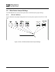
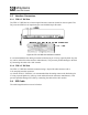
8 TROUBLESHOOTING The problems that arise in most installations are summarized below: • • • 9 Cables: o Homemade, short, flat ribbon cables with bad contacts or cheap cables o Mixing round cables with flat cables Cable Length: o Exceeds the limit specified in the standard o Cables are too long to support the transfer rate Device Address Conflict: o Adding a new device with an IDE setting identical to an existing device on the bus o Connection o Connecting a cable in reverse polarity HOW
HOW TO CONTACT US USA China M-Systems Inc. 8371 Central Ave, Suite A Newark CA 94560 Phone: +1-510-494-2090 Fax: +1-510-494-5545 M-Systems China Ltd. Room 121-122 Bldg. 2, International Commerce & Exhibition Ctr. Hong Hua Rd. Futian Free Trade Zone Shenzhen, China Phone: +86-755-8348-5218 Fax: +86-755-8348-5418 Europe Japan M-Systems Japan Inc. Asahi Seimei Gotanda Bldg., 3F 5-25-16 Higashi-Gotanda Shinagawa-ku Tokyo, 141-0022 Phone: +81-3-5423-8101 Fax: +81-3-5423-8102 Taiwan M-Systems Ltd.