
music communications system Finish-Out Instructions dmc1

dmc1
www.mssystems.com | 800.421.1587 | www.mssystems.com
Page
9
Important: Verify all cable run locations prior to connecting if they
were not labeled at rough-in. Incorrectly connecting cables to the
master, room stations or door stations may result in system damage.
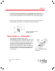
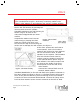
Install the optional chime module MC3 or
MC8 in the wall housing by pressing the
chime module over the 4 plastic
standoffs attached to the wall housing as
shown in figure 8. Refer to the
instructions shipped with the chime
module.
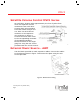
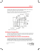
Suspend the master unit from the
wall housing by looping the third
hand wire (thick green wire) over
the hook at the top of the housing. Be
careful not to damage the wall surface. See figure 9.
If the dmc1 system has more than 9
room stations, some room selector
switches will control two room stations.
Do not exceed more than 15 total
speakers on the system. This limitation
does not include remote controls,
volume controls, speakers connected
to the optional stereo power amp, of
door stations. The station location can
be noted on the inside of the front
access panel on the left side of the
dmc1 master.
Connect the red and black wires of
the door station cables
(MS4DCX/MS4DCXSC) to the red and black door speaker terminals on
the dmc1 master as shown in figure 10. Insulate the bare wires using
some of the jacket material to prevent shorting to the circuit board.
Connect this wire to terminal labeled shield. Connect all orange wires
from the door stations to the common terminal on the MC3 or MC8.
Figure 8 - Chime module
installation
Figure 9 - Third hand assembly