
music communications system Finish-Out Instructions dmc1

dmc1
www.mssystems.com | 800.421.1587 | www.mssystems.com
Page
8
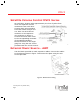
Door Stations
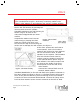
At each door station location, strip approximately 4
inches of jacket from wire and separate colored
conductors from one another. Strip ½ inch of
insulation from conductors as shown in figure 1. Cut
each shield drain wire at jacket to prevent them from
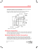
touching each other (MS4DCXSC only). Terminate
yellow and orange wires to the screw terminals on
the bell button (if equipped). Connect the red and
black wires to the red ban black wires on the speaker
respectively. Refer to figure 6. Mount door station to
housing using the two screws provided with the door
station.
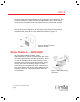
dmc1 Master Installation
Gather all room station and door station
cables and cut cable ends to the same
length approximately 12 inches from entry
point into wall housing. Make sure that all
cables remain properly labeled. Strip
approximately 2” of insulation from each of
the CAT5 cables. Untwist the individual wire
pairs. Insert each wire pair into the correct
connector location and close connector (see figure 7). Insert each
cable connector into its proper location on the dmc1 master. Note:
Verify that the outdoor patio speaker is connected into the Patios
station cables location only. If you are connecting two patio speakers,
use the screw terminal connectors provided with the dmc1RW for the
patio. Connect both patio stations cables into one screw terminal
connector.
Figure 6 - Door station
connections
Figure 7 - Connector
w
iring diagram