
music communications system Finish-Out Instructions dmc1

dmc1
www.mssystems.com | 800.421.1587 | www.mssystems.com
Page
13
dmc1
from
dmc1
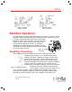
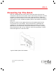
marked locations with the screws provided as shown in figure 17. FAILURE
TO PROPERLY MOUNT THE AMPLIFIER MAY LEAD TO AMPLIFIER DAMAGE AND
/OR
VOLUME CONTROL
/PREAMP WIRING DAMAGE.
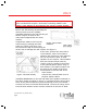
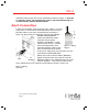
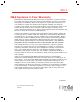
dmc1 Connection
Locate the MS7X5SC cable from the dmc1 master. Connect
each of the 7 colored wires and shield drain wire from the
MS7XSC cable to the 8 pin terminal block as shown in
figure 18. Plug the 8 pin connector into the jack labeled
PREAMP INTERCONNECT.
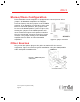
Locate the MS7X5SC cable
from the second power
amplifier (MC960PA), if used.
Connect each of the 7 colored
wires and shield drain wire
from the MS7XSC cable to the
8 pin terminal block as shown
in figure 18. Plug the 8 pin connector into the
jack labeled TO SECOND AMP.
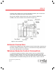
Gather all volume control cables (MS5XSC).
Pigtail all shield drain wires (bare) from the
MS5XSC cables to the SHIELD terminal on the
remote amplifier. Then connect each of the
color-coded wires to its respective terminals as shown in Figure 19.
Figure 18 – Wiring
dia
g
ram
Figure 19 – Wiring
connections