
User's Manual
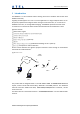
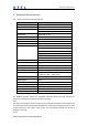
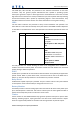
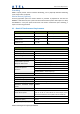
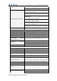
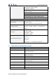
Table Of Contents

New Product Requirement
Asiatelco Technologies Co. Proprietary/Confidential
Two GPIO pins, GP1 and GP2, are presented to the external environment on the main
connector. They are general purpose bidirectional lines capable of providing system
interrupts to generate a report or drive logic levels to external devices. These lines are 2.8V
logic level and are 15V tolerant. These pins default to input. GP1 is pulled down representing
0 when disconnected; GP2 is pulled up representing logical 1 when disconnected. They
should be asserted to a known value if used. GP1 is intended to use for Ignition Sensing.
LED’s
Two LED status indicators are provided to verify correct installation and operation. The
status LEDs are color coded and directly convey the status of the CDMA and GPS subsystems
as described in the table below. Their valid operation also indicates operational status and
power.
LED Function Status
Red GPS On: GPS satellites acquired and
Locked
Flash Slow: GPS satellite search is
in progress
Off: No power or GPS subsystem
fault
Green CDMA/CDMA Connection On: Indicates CDMA connection is
made
Flash Slow: CDMA subsystem
initialized but no connection
Flash Fast: CDMA initialization in
process
Off: No power or CDMA
subsystem fault
The ION provides user control allowing the LEDs to be extinguished once installation is
verified. This feature reduces power and further conceals the ION Tracker from untrained
parties wishing to defeat its operation.
UART
A UART port is provided for AT command and data interaction and optionally for application
specific control. When in power down mode, a character must be sent to the UART first to
wake it up. The port will stay awake for 5 seconds after any character received.
Relay Driver
A 500mA sink capable output pin is provided. This pin is meant to drive a relay coil indented
to interrupt the starter solenoid relay for the ignition circuit to a car.
Battery Monitor
The battery monitor is internal analog input scaled such that the DC value of the power input
pin to the ION system is measured. This value is scaled to span the most significant 8 bits of
the A/D and consequently covers a scale from 0 to 25.5 Volts.
Timers
Timers resident on the CDMA baseband chip generate periodic interrupts for power down
wakeup, watchdog support, report generation and other timer related functions. Report
timers are supported by related AT command and cause generation of periodic reports.