
User Manual


28
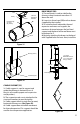
4. Good installation requires that expansion
greater that 1/4” must be compensated with
either a bellow joint (LB) or an adjustable
length (LA). Depending on the pressure of
the system.
5. Tees and elbows are not designed to
withstand bending moment, make sure
to compensate thermal expansion before
connecting to a tee or a elbow.
6. Expansion joints are not designed to
withstand lateral forces so they must be
accurately supported and guided.
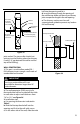
7. Because the amount of outer casing
movement is the same as the inner ue, the
outer casing must slide to avoid excessive
forces on tees, elbows or xed points. To
accommodate outer casing movements,
wall guide, oor guide and suspension bands
must allow movement of the chimney.
8. When supporting a system with
considerable height and thermal expansion,
adjustable lengths or bellow joints must be
used just below every xed support above the
rst to compensate for thermal expansion.
9. For engine or turbine exhaust system
requiring pressures up to 60 inches of water
column, or where the construction must
be absolutely gas tight, all welded bellows
length (LB) are recommended for expansion
and vibration movements of the exhaust.
10. Low pressure systems, such as boilers (up
to 6 inches water column), can eectively use
the Adjustable Length (LA).
11. Spacing of guides and supports, when a
thermal expansion part is used, should not
be greater than that specied in Section A,
Table 7.
12. Proper guiding and support of expansion
parts often requires closer spacing.
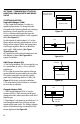
EXPANSION JOINTS INSTALLATION
Bellows Expansion Joint (LB) and Adjustable
Length (LA) in vertical runs
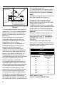
1. A Bellows Expansion Joints or Adjustable
Length installed vertically should be installed
directly below one chimney length of the
highest support, between xed points (see
Figure 50).
2. Always use Bellows Expansion Joints or
Adjustable Lengths between xed points
when expansion is over 1/4”. See Table 14
and Table 15 for maximum run between
xed points.
3. Install proper guiding between xed
points when using Bellows Expansion Joint or
Adjustable Length, to allow chimney vertical
movement due to expansion.
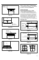
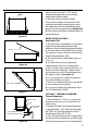
Figure 49
X min. = Expansion + E [inch]
Expansion = (length[feet]/100)x(ΔT[°F]/100)
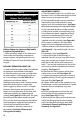
Table 14
Maximum Run With Bellow Between Each
Fixed Point
Operating Temp. (°F)
Max Distance With One
Bellow Joint (ft.)
700 42 /
800 37 ½
900 33 /
1000 30
1100 27 /
1200 25
1300 23 /
1400 21 /
Tee 45 RV
Anchor Plate in frame by others
ANSI Female Flange Adapter
Relief
Valve
Flue Direction