Operating Manual Gas sampling and gas conditioning technology 3-0.
Dear customer, we have made up this operating manual in such a way that all necessary information about the product can be found and understood quickly and easily. Should you still have any question, please do not hesitate to contact M&C directly or go through your appointed dealer. Respective contact addresses are to be found in the annexe to this operating manual. Please also contact our homepage www.mc-techgroup.com for further information about our products.
Content 1 General information ................................................................................................................... 4 2 Declaration of conformity ......................................................................................................... 4 3 Safety instructions ..................................................................................................................... 5 4 Warranty ........................................................................
Head Office M&C TechGroup Germany GmbH Rehhecke 79 40885 Ratingen Germany Telephone: 02102 / 935 - 0 Fax: 02102 / 935 - 111 E - mail: info@mc-techgroup.com www.mc-techgroup.com 1 GENERAL INFORMATION The product described in this operating manual has been examined before delivery and left our works in perfect condition related to safety regulations. In order to keep this condition and to guarantee a safe operation, it is important to heed the notes and prescriptions made in this operating manual.
3 SAFETY INSTRUCTIONS Please take care of the following basic safety procedures when mounting, starting up or operating this equipment: Read this operating manual before starting up and use of the equipment. The information and warnings given in this operating manual must be heeded. Any work on electrical equipment is only to be carried out by trained specialists as per the regulations currently in force.
5 USED TERMS AND SIGNAL INDICATIONS DANGER! This means that death, severe physical injuries and/or important material damages will occur in case the respective safety measures are not fulfilled. WARNING! This means that death, severe physical injuries and/or important material damages may occur in case the respective safety measures are not fulfilled. This means that minor physical injuries may occur in case the respective safety measures are not fulfilled.
6 INTRODUCTION The VC-... pre-cooling units produced by M&C incorporates the “Jet-Stream’’ design of heat exchanger. This design induces condensate formation and guarantees optimum dew point reduction to ambient temperature. 7 APPLICATION The M&C pre-cooling units VC-...
9 DESCRIPTION The condensate formed should be removed with a small peristaltic pump, sample trap or collection vessel. The VC-..-SL pre-cooling unit has as a standard peristaltic pumps SR25.1 for automatic condensate removal. The VC-..-..L pre-cooling unit has got a fan to force the ventilation of the cooling fins for performance rise. In this case, a deflector is integrated for an optimal air conduction. The VC-1-.. pre-cooling unit is equipped with one EC-Jet-Stream heat exchanger. The VC-2-..
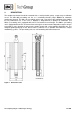
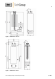
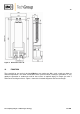
Figure 2 Dimensions VC-1-SL Figure 3 Dimensions VC-2-L Gas sampling and gas conditioning technology 3-0.
Figure 4 10 Dimensions VC-2-SL FUNCTION The especially for gas analysis designed M&C gas pre-cooler type VC-.. cools sample gas down to ambient temperature. The novel construction of the jet-stream heat exchangers guarantees a very good pre-separation of condensate and for that reason an optimal drying of sample gas with a minimum of washing out effects. Figure 3 shows the functional diagram of the heat exchanger. Gas sampling and gas conditioning technology 3-0.
Sample OUT Sample IN Cooling block +5°C Condensate OUT Figure 5 11 Schematic diagram of the heat exchanger function RECEPTION AND STORAGE The gas cooler VC-.. are complete pre-installed units.
12 INSTALLATION INSTRUCTIONS The cooler VC-.. is suitable for wall mounting. Mounting dimensions see figure 1-4. NOTE! Unheated gas sample lines must be provided with slope up to the cooler. Connect the heated sample line with sufficient thermal decoupling of min. 20cm to the cooler! 13 SUPPLY CONNECTIONS 13.1 HOSE CONNECTIONS The connection for sample gas inlet and outlet happens at the GL-connectors on the upper part of the heat exchangers.
13.2 ELECTRICAL CONNECTIONS CARE! NOTE! When connecting the equipment, please ensure that the supply voltage is identical with the information provided on the model type plate! Attention must be paid to the requirements of IEC 364 (DIN VDE 0100) when setting high-power electrical units with nominal voltages of up to 1000V, together with the associated standards and stipulations. An external main switch must be provided.
14 START-UP The following steps should be carried out before initial start-up: 15 Connect the cooler unit to the mains power supply (except VC-1); Check that the equipment is connected to the correct mains voltage, 115V or 230V, as shown on the type plate. CLOSING DOWN NOTE! CARE! 16 The location for the cooler must remain frost-free, even when the unit has been switched off! If the cooler unit is putting out of action for a short time no particular measures need to be taken.
16.2 MAINTENANCE OF THE PERISTALTIC PUMP(S), TYPE SR25.1 AND SR25.2 Before the maintenance work is carried out, it is necessary that the specific safety procedures pertaining to the system and operational process are observed ! DANGER Dangerous voltage ! It is necessary to take the pump off the mains before any assembly, maintenance and repair work is carried out ! Flexible tube, conveying belt, contact pulleys and contact springs are the only parts of the pump subject to wear.
Take away conveying belt and remove the old hose set from the guides by the hose connectors; Press the two contact pulleys and check whether the spring pressure is still sufficient, if not, the contact springs have to be changed (see 16.2.2); Put the new hose set with the hose connectors into the guides of the conveying belt ; NOTE! Only the usage of the original hose set guarantees a perfect function. Never lubricate the hose.
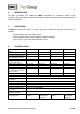
17 SPARE PARTS LIST Wear, tear and replacement part requirements depend on specific operating conditions. The recommended quantities are based on experience and they are not binding. Electric gas cooler VC-.. (C) Consumable parts (R) Recommended spare parts (S) Spare parts Part No. Indication 02 K 9100 Jet-stream heat exchanger type EC-G. Material: Duran-glass. Connections: Sample gas: 2x GL18-6mm, Condensate: 1x GL25-12mm Thermal conductivity paste, -20 to +140°C, silicon free, 50gr.
18 APPENDIX Further product documentation can be seen and downloaded from our home page: www.mc-techgroup.com Threaded couplings for ”GL” glass connections Document: 3-5.1.1 Instruction manual peristaltic pump SR25.1 Document: 3-7.1ME Automatic liquid drain AD-SS Document: 3-6.2.3 Automatic liquid drain AD-P Document: 3-6.2.1 Condensate vessel TG, TK Document: 3-6.3.1 Gas sampling and gas conditioning technology 3-0.