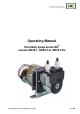
Operating Manual Peristaltic pump series SR® version SR25.1, SR25.2-G, SR25.1/Ex Gas sampling and gas conditioning technology 3-7.
Dear customer, we have made up this operating manual in such a way that all necessary information about the product can be found and understood quickly and easily. Should you still have any question, please do not hesitate to contact M&C directly or go through your appointed dealer. Respective contact addresses are to be found in the annexe to this operating manual. Please also contact our homepage www.mc-techgroup.com for further information about our products.
Content 1 General information.................................................................................................................... 4 2 Declaration of conformity .......................................................................................................... 4 3 Safety instructions ..................................................................................................................... 5 4 Warranty ..........................................................................
Head Office M&C TechGroup Germany GmbH Rehhecke 79 40885 Ratingen Germany Telephone: 02102 / 935 - 0 Fax: 02102 / 935 - 111 E - mail: info@mc-techgroup.com www.mc-techgroup.com 1 GENERAL INFORMATION The product described in this operating manual has been examined before delivery and left our works in perfect condition related to safety regulations. In order to keep this condition and to guarantee a safe operation, it is important to heed the notes and prescriptions made in this operating manual.
3 SAFETY INSTRUCTIONS Please take care of the following basic safety procedures when mounting, starting up or operating this equipment: Read this operating manual before starting up and use of the equipment. The information and warnings given in this operating manual must be heeded. Any work on electrical equipment is only to be carried out by trained specialists as per the regulations currently in force.
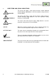
USED TERMS AND SIGNAL INDICATIONS 5 DANGER! This means that death, severe physical injuries and/or important material damages will occur in case the respective safety measures are not fulfilled. WARNING! This means that death, severe physical injuries and/or important material damages may occur in case the respective safety measures are not fulfilled. This means that minor physical injuries may occur in case the respective safety measures are not fulfilled.
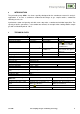
6 INTRODUCTION The peristaltic pump SR25... has been specially developed for the condensate removal in analysis applications. It ensures a continuous condensate discharge at gas sample coolers, condensate collecting vessels, etc. Synchronous motor and gearing unit with return stop make a condensate backflow impossible. The capacity of 0,3l/hr guarantees a safe condensate removal, for example when cooling 850l/hr sample gas with an inlet dew point of +70°C.
DESCRIPTION 8 The peristaltic pump SR25.1 is self-suctioning and designed for continuous operation. It consists of 3 compact parts: synchronous motor, gearing unit with return stop, pump. The slow speed (5rpm) of the two PVDF hose contact pulleys together with the novoprene hose guarantee a good mechanical and chemical resistance with a long service life. NOTE! The compatibility of the tube material with unknown gases has to be checked before using.
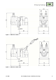
Figure 2 Dimensions SR25.1 Figure 3 Dimensions SR25.1/EX 3-7.
Figure 4 Dimensions SR25.2-G RECEPTION AND STORAGE 9 The peristaltic pump is a complete pre-installed unit.
DANGER! NOTE! The peristaltic pumps SR25.1 and SR25.2-G must not be operated in hazardous areas. The pump must only be used in the conditions specified in the technical data. The pump should be installed away from heat sources and freely ventilated to prevent any accumulation of heat. For outdoor installation, the pump must be installed in a housing protected from frost in the winter and sufficiently ventilated in summer. Exposure to direct sunlight must be avoided.
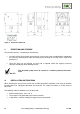
The tightness of the connections can only be guaranteed if the connection hose has a straight rim (hose cutter). NOTE! CARE! 11.2 Aggressive condensate is possible! Wear protective glasses and proper protective clothing! ELECTRICAL CONNECTIONS Connect the cables for the power supply as follows: Power Power Figure 5 Connection of the distribution voltage Incorrect system voltage can damage the unit.
DANGER! The respective cable which is left (230 V white and 115 V red) must be connected at a separate clamp. The main circuit of the pump type SR25.1, SR25.1/EX and SR25.
MAINTENANCE 14 Before the maintenance work is carried out, it is necessary that the specific safety procedures pertaining to the system and operational process are observed! Dangerous voltage ! It is necessary to take the pump off the mains before any assembly, DANGER! maintenance or repair work is carried out ! Flexible tube, conveying belt, contact pulleys and contact springs are the only parts of the pump subject to wear. They are simple to change. NOTE! 14.
Take away conveying belt and remove the old hose set from the guides by the hose connectors; Press the two contact pulleys and check whether the spring pressure is still sufficient, if not, the contact springs have to be changed see (14.
The dent prevents rotation of the axis worn out Figure 8 Check of axes and rolls NOTE! NOTE! The springs may occur in different coulerings. This does not constitute a quality defect. But make sure that the right spring strength is used. This can be identified by the spring wire diameter. The „standard version for Novoprene pump hoses“ (part no. 90P1010) has a diameter of 1,1mm and the strengthened version for FPM-, Acidflex- or Masterflex-hoses“ (part no. 90P1015) has a diameter of 1,2mm.
14.2.1 CLEANING THE PUMP HEAD When changing flexible tube or other parts, inspect all parts for dirt before assembling the pump head and clean them if necessary. As far as possible clean the parts with a dry cloth. Solvents should not be used as they can attack the plastics and synthetic rubber parts. If a compressed air line is available, blow the parts out with it.
17 APPENDIX Spare part drawings SR25.1 and SR25.2 EC-type examination certificate SR25.1/EX, SR25.2/EX and SR25.3/EX Further product documentation can be seen and downloaded from our home page: www.mc-techgroup.com 18 Gas sampling and gas conditioning technology 3-7.
Figure 9 3-7.1-ME Spare part drawing SR25.
Figure 10 20 Spare part drawing SR25.2 Gas sampling and gas conditioning technology 3-7.
Figure 11 3-7.1-ME EC-type examination certificate SR25.1/EX, SR25.2/EX and SR25.
Gas sampling and gas conditioning technology 3-7.