Operating Manual Gas sample probe Series SP® Version SP3200V /.../HEX5-x.08 Version SP3200 /.../RS/HEX5-x.08 II 3 GD Gas sampling and gas conditioning technology 2-1.3.
Contents 1 2 3 4 5 6 7 8 Equipment standard ........................................................................................................................... 3 Safety information .............................................................................................................................. 3 Information on the use in hazardous areas ...................................................................................... 4 Guarantee ....................................................
1 EQUIPMENT STANDARD The equipment standard of the gas sample probe and the options correspond to the safety requirements of EC Directive 94/9/EG. The respective type of protection depends on the variant (see table 4). Manufacturer: M&C TechGroup GmbH Rehhecke 79 40885 Ratingen – Germany Tel.: 02102/935-0 E-Mail: info@mc-techgroup.com www.mc-techgroup.com 2 SAFETY INFORMATION Please observe the following fundamental safety precautions when using the device: 2-1.3.
3 INFORMATION ON THE USE IN HAZARDOUS AREAS Please see the identification of the individual variants in table 4. Detailed information and a copy of the declaration of conformity are contained in the appendix to these operating instructions. The devices must be installed and used in accordance with the conditions and installation instructions given in the EX-Certificate (see appendix). Only then, a safe operation in hazardous areas is guaranteed.
6 APPLICATION The probes of type SP3200V.. and SP3200.. are used for continuous gas sampling in dust-laden processes or processes with high temperatures (according to table 5, chapter 10) or high gas moisture. The modular construction of the probes and the variety of possible options guarantee optimum adaptation of the probes to complex process and environmental conditions. The probes of the type SP3200V.. and SP3200.. are available in both, an unheated and an electrically heated version.
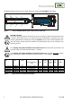
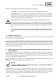
The following figure shows the basic version of the gas sample probe SP3200(V) with prefilter. Figure 1 Probe SP3200(V) without options with preliminary filter V20 SP3200V / SP3200: In case the gas-dust mixture to be examined must be classified as potentially explosive because it contains combustible gases, only downstream devices (flowmeters, analysers) with corresponding identification according to directive 94/9/EC must be used. Suitable explosion isolation with a flame arrestor must be established.
Type Part-Nr. Material Dimension [mm] 1.
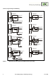
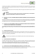
Scheme test gas feeding or backflushing Entnahmesonde Sample Probe Entnahmesonde Sample Probe Meßgasausgang Sample out Meßgasausgang Sample out Option R / BB Option CCF Prüfgas/Rückspülung Cal. gas/ pure gas Entnahmesonde Sample Probe Entnahmesonde Sample Probe Meßgasausgang Sample out Meßgasausgang Sample out Option VA Option BBF Option CC Prüfgas/Rückspülung Cal.
General safety instructions for back flushing and feeding of calibration gas A backflushing gas suitable for the sampling point must be selected for backflushing. The backflushing pressure / calibration gas pressure must always be higher than the process pressure. This minimum pressure must be monitored with a press switch at the inlet side of the accumulator or the check valve. If the flush gas pressure drops below the process pressure, the backflushing solenoid valve must not be operated.
In principle, you need only a small quantity of test gas for probes with an integrated ball valve, because the probe is separated from the process when the ball valve is activated so that there is no danger of a mixture with the process gas. In case of manual operation, please turn the turning handle to the right side until the limit stop in order to shut off the probe.
This kind of gas feeding provides the advantage that during backflushing the downstream analyse system is automatically separated from the probe respectively, the probe is automatically separated from the process during test gas feeding. For that reason, you need a lower quantity of test gas as no mixture with the process gas may occur. For the measuring operation, the ball valve must be put into the central position. For backflushing, the ball valve must be put into the corresponding position.
8.11 PROBE HEATING The probe heating type HEX5-x.08 is suitable for temperature ranges of 85°C -185°C. It consists of a heating plate with heating cartridges and a control electronic. For the heater type HEX5.1.08, the control electronic is mounted onto the probe. This means a range of the ambient temperature for the probe of 0 – 50°C. The probe heating type HEX5.2.08 is designed for an external mounting of the control unit (in Ex zone 2).
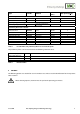
Temperature controller II3G Ex nA nC nL IIC T5 to T2 II3D Ex tD A22 IP65 T75°C to T235°C Class I, Div. 2, Groups A/B/C/D T5 – T2B Admissible medium temperature on the probe The admissible medium temperature is limited by the materials used (< 200°C) inlet and by the maximum admissible surface temperatures as shown in table 4. Power max. 800 W (240V), max. 830 W (120V) Case protection IP65; EN60529 Operating temperature 0°C to max. 230°C according to T-class, pls. indicate with order.
Part No. 20S9045 + 20S9012 Way of test gas /R/CC = via sample gas outlet or /R/CCF = via probe filter element Check valve /R check valve 1/4” Opening pressure >0,7 bar Connection 6mm tube Maximum blow back pressure 6 bar abs. Maximum operating temperature +185 °C Option high performance blow back valve /BB /BBF Part No.
The intended use of the probe restricts the process medium temperature at the probe inlet and the choice of options to the extent that the maximum surface temperature must lie below the temperature limit given in table 5 for the combustible gases used or must correspond to the temperature class of the combustible gases used. Gas sample probe SP3200(V) for gas sampling out o f processes with combustible gases Identification Variants SP3200(V)/HEX5-x.08 II 3 G and all options Table 4 Max.
First make sure that conditions at the intended place of use correspond to the data on the rating plate. The temperature of the process must be taken into account when selecting the sampling point. Heating of the probe above the temperature limit given in table 5 must be prevented. It must be ensured that the temperature class of the probe corresponds to the ignition temperatures of the combustible gases/vapours.
Work on the gas sample probe may only be carried out when the process and environment have been declared to non-hazardous areas, i.e. they are free of explosive atmospheres. The following procedure is recommended: Remove the probe cover after opening the two toggle-type fasteners. Figure 4 Schematic drawing of the filter housing cover Turn handle A about one full turn anticlockwise so that the cover is lifted. Place handle C in position E.
Figure 5 Removal of the filter housing cover Check that the filter element is screwed on firmly. Insert the filter holder part again. The filter holder part is closed in reverse order. Push the ¾" flat gasket on to the thread of the preliminary filter or extension tube, screw the filter or tube into the ¾” internal thread in the flange and tighten.
moved completely and then refitted. Then check the connection for leaks. The sample line is connected as follows: Loosen the toggle-type fasteners on the isolating cover and remove the cover. Loosen the thumb screw of the heat conducting plates and remove the plates. Screw a suitable union into the probe head using sealing tape. Remove the top part of the sample line mounting clamp and insert the sample line through the silicon cap in the bottom part of the bracket plate and into the union.
At sampling points with inerting, backflushing must be performed with corresponding inert gas. It must be ensured that the inert gas does not introduce oxygen or combustible gases into the system. The backflushing pressure must not exceed 6 bar abs..
The solenoid valve should be operated cyclically every 60 minutes (carry out min. 1 pulse/s). Please read the electrical connection of the heating in the separate operating instructions of the heating HEX5-x.08. 14 STARTING-UP The requirements of VDE 0100 and its associated standards and regulations must be observed when erecting high-voltage power installations with rated voltages of up to 1000 V. An external main switch must be provided.
The gas sample probe with preliminary filter and internal filter must be checked for temperature and dust deposits in suitable intervals of time depending on the process conditions. Dust layers of more than 5 mm must be removed immediately. The filters must be checked for damage and replaced if necessary. Also remove the dust deposits under the cover. The probe must be shut down when the respective maximum surface temperature is exceeded.
16 SHUTDOWN Before shutdown, i.e. switching off the heater, the probe should be flushed with a suitable inert gas to prevent condensation of aggressive components of the process gas. 17 SPARE PARTS LIST Wear, tear and replacement part requirements depend on specific operating conditions. The recommended quantities are based on experience and they are not binding.
Figure 6 24 SP3200 RS, HEX5-1.08 Gas sampling and gas conditioning technology 2-1.3.
Figure 7 2-1.3.9-ME SP3200 RS, HEX5-2.
Gas sampling and gas conditioning technology 2-1.3.
2-1.3.
Gas sampling and gas conditioning technology 2-1.3.