
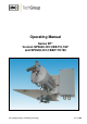
Operator's manual Manual

3
Gas sampling and gas conditioning technology 2-1.1.5.1-ME
Contents
1 General information ............................................................................................................... 4
2 Declaration of conformity ...................................................................................................... 4
3 Safety instructions ................................................................................................................. 5
4 Warranty .................................................................................................................................. 5
5 Used terms and signal indications ....................................................................................... 6
6 Introduction ............................................................................................................................. 7
6.1 Serial Number ................................................................................................................. 7
7 Application .............................................................................................................................. 7
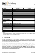
8 Technical data ......................................................................................................................... 8
9 Description .............................................................................................................................. 8
9.1 Options ............................................................................................................................ 9
10 Receipt of goods and storage ............................................................................................. 10
11 Installation and dimensions ................................................................................................ 10
12 Mounting ............................................................................................................................... 12
12.1 Mounting of the prefilter respectively the sample tube .................................................. 12
12.2 Mounting of the probe ................................................................................................... 12
12.3 Dismounting of the filter housing cover and checking the filter element ........................ 13
13 Supply connections ............................................................................................................. 14
13.1 Pneumatic connection ................................................................................................... 14
13.1.1 Connection of the sample line ............................................................................... 14
13.1.2 Connection of the backpurge and calibration gas ................................................. 15
13.2 Electrical connection ..................................................................................................... 15
13.2.1 Version with internal capillary tube thermostat ...................................................... 16
13.2.2 Version with external temperature regulator .......................................................... 16
14 Starting .................................................................................................................................. 17
15 Closing down ........................................................................................................................ 17
16 Maintenance and repair ....................................................................................................... 18
16.1 Change of the filter element and the sealings ............................................................... 18
17 Spare parts list ...................................................................................................................... 19
18 Annex ..................................................................................................................................... 19
List of illustrations
Figure 1 Construction and dimensions of the SP2600-H/C/I/BB/F/1K190 ............................... 11
Figure 2 Construction and dimensions of the SP2600-H/C/I/BB/F/0,1GF ............................... 11
Figure 3 Mounting of the pre-filter or sample tube ................................................................... 12
Figure 4 Schematic drawing of the filter housing cover ........................................................... 13
Figure 5 Dismounting of the filter housing cover ..................................................................... 14