Operating Manual Series SP® Version SP2600-H/C/I/BB/F/0,1GF and SP2600-H/C/I/BB/F/1K190 Gas sampling and gas conditioning technology 2-1.1.5.
Dear customer, we have made up this operating manual in such a way that all necessary information about the product can be found and understood quickly and easily. Should you still have any question, please do not hesitate to contact M&C directly or go through your appointed dealer. Respective contact addresses are to be found in the annexe to this operating manual. Please also contact our homepage www.mc-techgroup.com for further information about our products.
Contents 1 2 3 4 5 6 General information ............................................................................................................... 4 Declaration of conformity ...................................................................................................... 4 Safety instructions ................................................................................................................. 5 Warranty .............................................................................
Head Office M&C TechGroup Germany GmbH Rehhecke 79 40885 Ratingen Germany Telephone: 02102 / 935 - 0 Fax: 02102 / 935 - 111 E - mail: info@mc-techgroup.com www.mc-techgroup.com 1 GENERAL INFORMATION The product described in this operating manual has been examined before delivery and left our works in perfect condition related to safety regulations. In order to keep this condition and to guarantee a safe operation, it is important to heed the notes and prescriptions made in this operating manual.
3 SAFETY INSTRUCTIONS Please take care of the following basic safety procedures when mounting, starting up or operating this equipment: Read this operating manual before starting up and use of the equipment. The information and warnings given in this operating manual must be heeded. Any work on electrical equipment is only to be carried out by trained specialists as per the regulations currently in force.
5 USED TERMS AND SIGNAL INDICATIONS DANGER! This means that death, severe physical injuries and/or important material damages will occur in case the respective safety measures are not fulfilled. WARNING! This means that death, severe physical injuries and/or important material damages may occur in case the respective safety measures are not fulfilled. This means that minor physical injuries may occur in case the respective safety measures are not fulfilled.
6 INTRODUCTION The M&C gas sample probes type SP2600-H.. are based on the patented probe SP2000-H and are used for continuous gas sampling in processes with a high extent of dust, high temperature and/or high gas moisture. 6.1 SERIAL NUMBER The type plates are to be found where the electrical connection box is placed. NOTE! 7 Please indicate the serial number of the equipment in case of any question and when ordering spare parts.
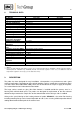
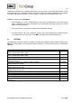
8 TECHNICAL DATA Technical Data Series SP ® Part Number Integrated back purging Weather protection cap Protection terminal box Materials filter housing Sealing material Material probe flange sealing Sample tube Sampling pressure max.
Temperature control of the standard version takes place by means of an integrated capillary sensor thermostat with excess temperature limiter and alarm function for insufficient temperature in a compact arrangement directly on the probe. Test gas feeding is possible via an integrated check valve. Additional functions of the SP2600-H..: 9.1 The calibration gas can be supplied directly at the check valve/C (return valve) to the probe outlet.
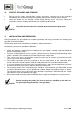
10 RECEIPT OF GOODS AND STORAGE Please take the probe and possible special accessories carefully out of the packaging immediately after receipt and compare the goods with the items listed on the packing list. Check the goods for any damage caused during delivery and, if necessary, notify your transport insurance company without delay of any damage discovered.
Figure 1 Construction and dimensions of the SP2600-H/C/I/BB/F/1K190 Figure 2 Construction and dimensions of the SP2600-H/C/I/BB/F/0,1GF Gas sampling and gas conditioning technology 2-1.1.5.
12 MOUNTING The M&C probes SP2600-H.. are designed for stationary use and provide a long service life and a minimum of maintenance work under the premise of professional selection of the sampling point and professional mounting. 12.1 MOUNTING OF THE PREFILTER RESPECTIVELY THE SAMPLE TUBE The pre-filter or sample tube is mounted together with a suitable sealing by screwing into the G ¾“ thread of the probe flange. Figure 3 12.
12.3 DISMOUNTING OF THE FILTER HOUSING COVER AND CHECKING THE FILTER ELEMENT The filter housing cover is dismounted as followed: Figure 4 Schematic drawing of the filter housing cover Turn the toggle handle A approximately one rotation to the left side so that the cover is lifted; Put the handle C into position E; Turn the clamp clip B to the left side (direction G); Pull out the filter housing cover with the toggle handle A. The photos shall illustrate the above mentioned steps.
Figure 5 Dismounting of the filter housing cover Now, the filter element is visible. Check on the filter pressing screw whether the filter element is screwed on tightly. Push the cover with filter element into the probe again. Turn the clamp clip B to the right side and bring the ring bolt D into position E by using the handle C so that the clamp clip locks into place of the ring bolt D and the threaded bolt H.
Insert the line through the corresponding opening in the bottom of the probe and through the silicone retainer; Connect the line to the tube joint.
NOTE! For the erection of high-power electrical units with nominal voltages of up to 1000V, the requirements of VDE 0100 (IEC 364) must be observed together with the associated standards and stipulations. A main switch must be provided externally. The main circuit of the device must be equipped with a fuse corresponding to the nominal voltage (over current protection); for electrical details see technical data.
14 STARTING Before starting the equipment for the first time, the safety instructions related to the installation and the process have to be heeded. Please consider the appropriate safety requirements and respective measures regarding the mediums to be extracted. WARNING! Please ensure before starting that the mains supply corresponds to the indication on the type plate ! Be careful when you get in contact with the probe’s surface during operation. The high surface temperatures may cause burnings.
16 MAINTENANCE AND REPAIR Before carrying out any maintenance and repair work, the specific installation and process safety measures are to be observed. Aggressive condensat is possible. Wear protective glasses and appropriate protecting clothes ! WARNING! Attention must be paid when touching the probe surface during operation. Due to the high surface temperatures, you may suffer from burnings.
NOTE! 17 Pay attention that after putting in the filter housing lid the strap bolt is screwed down hand-tight in cold condition and that it is tightened again after the operating temperature is reached. SPARE PARTS LIST Wear, tear and replacement part requirements depend on the specific operating conditions. The following table shows an extract of the recommended spare parts for probe of type SP2600-H.. . Recommended spare parts Part-No.