
User Manual

2
Gas sampling and gas conditioning technology 2-1.1.5-ME
Contents
1 General information ....................................................................................................................... 4
2 Declaration of conformity ............................................................................................................. 4
3 Safety instructions ......................................................................................................................... 5
4 Warranty ......................................................................................................................................... 5
5 Used terms and signal indications ............................................................................................... 6
6 Introduction .................................................................................................................................... 7
7 Description ..................................................................................................................................... 7
7.1 Options ................................................................................................................................... 10
8 Technical data .............................................................................................................................. 11
9 Dimensions ................................................................................................................................... 12
10 Receipt and storage ..................................................................................................................... 12
11 Installation information ............................................................................................................... 12
12 Installation .................................................................................................................................... 13
12.1 Probe assembly ...................................................................................................................... 13
12.2 Fitting preliminary filter or sample tube ................................................................................... 14
12.3 Connection of sample line ...................................................................................................... 16
12.4 Connection of backflushing and calibration gas line ............................................................... 17
12.5 Electrical connection ............................................................................................................... 17
12.5.1 Versions with internal capillary tube thermostat .............................................................. 18
12.5.2 Version with external thermostat ..................................................................................... 18
13 Starting ......................................................................................................................................... 19
14 Closing down ............................................................................................................................... 20
15 Maintenance ................................................................................................................................. 20
15.1 Replacement of filter element and seals ................................................................................ 21
16 Spare parts list ............................................................................................................................. 22
17 Annex ............................................................................................................................................ 22
List of illustrations
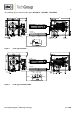
Figure 1 Probe type SP2500-H ...................................................................................................... 8
Figure 2 Probe type SP2500-H/C/I/BB ........................................................................................... 8
Figure 3 Probe type SP2500-H/C/I/BB/F ........................................................................................ 9
Figure 4 Dimensions (mm) of SP2500-H.. probe ......................................................................... 12
Figure 5 Schematic diagram of filter housing cover ..................................................................... 14
Figure 6 Removal of filter housing cover ...................................................................................... 15
Figure 7 Fitting preliminary filter or sample tube .......................................................................... 15