Operating instructions Gas sample probe series SP® Versions SP2500-H, SP2500-H/C/I/BB SP2500-H/C/I/BB/F Gas sampling and gas conditioning technology 2-1.1.
Contents 1 2 3 4 5 6 7 General information .......................................................................................................................4 Declaration of conformity .............................................................................................................4 Safety instructions .........................................................................................................................5 Warranty .......................................................
Dear customer, we have made up this operating manual in such a way that all necessary information about the product can be found and understood quickly and easily. Should you still have any question, please do not hesitate to contact M&C directly or go through your appointed dealer. Respective contact addresses are to be found in the annexe to this operating manual. Please also contact our homepage www.mc-techgroup.com for further information about our products.
Head Office M&C TechGroup Germany GmbH Rehhecke 79 40885 Ratingen Germany Telephone: 02102 / 935 - 0 Fax: 02102 / 935 - 111 E - mail: info@mc-techgroup.com www.mc-techgroup.com 1 GENERAL INFORMATION The product described in this operating manual has been examined before delivery and left our works in perfect condition related to safety regulations.
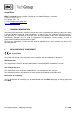
3 SAFETY INSTRUCTIONS Please take care of the following basic safety procedures when mounting, starting up or operating this equipment: Read this operating manual before starting up and use of the equipment. The information and warnings given in this operating manual must be heeded. Any work on electrical equipment is only to be carried out by trained specialists as per the regulations currently in force.
5 USED TERMS AND SIGNAL INDICATIONS DANGER! This means that death, severe physical injuries and/or important material damages will occur in case the respective safety measures are not fulfilled. WARNING! This means that death, severe physical injuries and/or important material damages may occur in case the respective safety measures are not fulfilled. This means that minor physical injuries may occur in case the respective safety measures are not fulfilled.
6 INTRODUCTION M&C SP2500-H.. series probes are used for continuous gas sampling in dust-loaded processes at high temperatures and high gas moisture. The probe offers the possibility to remove the preliminary filter or sample tube in the process without having to remove the probe head for cleaning purposes. H/C/I/BB and ..-H/C/I/BB/F series probes are used in highly dust-loaded processes.
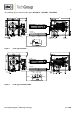
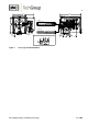
The following figures show the probe types SP2500-H, ...H/C/I/BB, ...H/C/I/BB/F. 207 340 345 Option: C 110 Pre-filter 260 Sample tube Power Low temperature 230V,50Hz alarm (115V,60Hz) Tube 6x1 Option: Test gas >0,7bar Option: CTest gas IN Sample IN 1/4" NPTi Option: 2x Option: 2x 2.
340 345 207 110 Pre-filter 260 Sample tube Power Low temperature 230V,50Hz alarm (115V,60Hz) Tube 8x1 Tube 6x1 Backflush 2-6bar Backflush IN Sample IN Control 3-10bar Test gas >0,7bar Test gas IN 1/4" NPTi Sample OUT 1/8" NPTi Control IN Backflush IN Sample OUT 180°C Figure 3 Probe type SP2500-H/C/I/BB/F Gas sampling and gas conditioning technology 2-1.1.
7.1 OPTIONS The following list shows the options available. The diversity of options and modular design of M&C gas sample probes ensure optimum probe selection to suit the particular process and ambient conditions. Description Basic typeSP2500H, heated to 0-180°C, with weatherproof cover, Material stainless steel 1.4571 Basic type SP2500-H/C/I/BB, heated to 180°C, with weatherproof cover, Material stainless steel 1.
8 TECHNICAL DATA Technical data SP ® series Article number Integrated backflushing Weatherproof cover Electrical connection Degree of protection of terminal box Power supply Material of medium contacted parts Ambient temperature Operating temperature Process pressure Ready for operation Alarm contact rating Sample gas outlet connection Calibration gas backflushing connection Isolating valve/I connection Control air pressure range SP2500-H/C/I/BB SP2500-H/C/I/BB/F 20 S 3520 20 S 3530 Via filter space
9 DIMENSIONS The following illustration shows the dimensions of the SP2500-H.. probe. 340 207 345 110 260 Figure 4 10 Dimensions (mm) of SP2500-H.. probe RECEIPT AND STORAGE The probe and any special accessories should immediately be unpacked carefully upon delivery and against the delivery note. The delivery should be checked for any transport damage and the transport insurer immediately notified of any damage. The probe should be stored protected from frost.
The nozzle mounting flange connection should be DN65 PN6 or 3“ANSI (115V version). For other connection dimensions, an optional intermediate flange adapter is available. The necessary, minimum flange sizes or minimal nozzle diameter depends on the sample tube used or the preliminary filter diameter. It is recommended to mount the probe horizontally with an angle of inclination of 10° with respect to the process.
12.2 FITTING PRELIMINARY FILTER OR SAMPLE TUBE The SP2500-H.. probe offers the possibility of fitting or removing the preliminary filter or sample tube in the process without having to remove the probe head. For this purpose, the filter housing covers must be removed as follows: Figure 5 Schematic diagram of filter housing cover Turn handle A about one full turn anticlockwise, so that the cover is lifted. Place handle C in position E.
The following figures show the described steps. Figure 6 Removal of filter housing cover Fitting of the preliminary filter or sample tube takes place as follows: Unscrew the mounting adapter for the preliminary filter or sample tube from the filter housing cover . Figure 7 Fitting preliminary filter or sample tube The filter element is now visible. Check that the filter element is screwed tight and then screw on the mounting adapter again.
Push the filter housing cover with preliminary filter or sample tube into the filter space in the probe head. Swing clamp B to the right and with handle C bring eye bolt D in position E, so that the clamp engages in eye bolt D and threaded bolt H; if necessary, push in or pull out the filter housing cover slightly with the clamping screw A; Turn handle C into position F and tighten handle A hand-tight by turning clockwise. 12.
12.4 CONNECTION OF BACKFLUSHING AND CALIBRATION GAS LINE ATTENTION! The backflushing pressure must be higher than the process pressure. Pay attention to the maximum pressure level (see technical data). SP2500-H: For option “C”, a check valve is fitted (see Figure 1, opening pressure 0.7bar). Connection of the backflushing or calibration gas line takes place on the underside of the probe. Provided for this purpose is a tube with the dimensions Ø8 x 1mm.
12.5.1 VERSIONS WITH INTERNAL CAPILLARY TUBE THERMOSTAT Remove the connection box cover. The electrical wiring diagram shown is contained in the cover. Insert the mains cable (min. 3 x 1.5 mm2 ) through the cable gland and connect to the appropriate terminals. Insert the signal cable (low temperature alarm) through the cable entry and connect to the appropriate terminals (contact position Tu indicates alarm). Screw the cover back in place again.
13 STARTING Prior to starting the device, the system and process-specific safety measures must be observed. For the media to be supplied, the relevant safety requirements and measures must be taken into account.
14 CLOSING DOWN Prior to closing down, i.e. switching off the heating, the probe should be flushed with inter gas or air in order to prevent the condensation of aggressive components from the process gas. 15 MAINTENANCE Prior to carrying out maintenance and repairs, the system and process-specific safety measures must be observed. Beware of aggressive condensate.
15.1 REPLACEMENT OF FILTER ELEMENT AND SEALS WARNING! Prior to carrying out maintenance and repairs, it must be ensured that no health-endangering contaminants remain in the probe. An appropriate measure is to flush the probe with inert gas, for example.
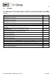
16 SPARE PARTS LIST The wearing and spare parts required depend on the specific operating conditions. The following table contains some recommended spare parts for SP2500-H/.. . series probes Recommended spare part Article No.