
Operator's manual User Manual

2-1.1-ME Gas sampling and gas conditioning technology 39
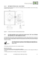
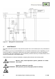
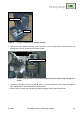
Figure 20 Position of Thermostat and heating cartridge
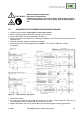
Unscrew the two hexagon head cap screws A (figure 21) in the back board of the connection box
with which this one is mounted to the retaining plate.
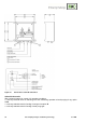
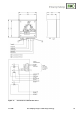
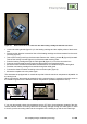
Figure 21 Position of fixing screws of connection box, thermostat sensor and heating cartridge carri-
er plate
Unscrew the hexagon head cap screws B (figure 21) for the fastening of the heating cartridge re-
taining plate and the thermostat sensor retaining plate.
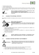
Remove the connection box including the heater cartridge and the thermostat sensor.
Heating cartridge
Thermostat
Hexagon screws A
Hexagon screws B
Cable gland C