
Operator's manual User Manual
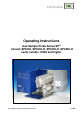

2 Gas sampling and gas conditioning technology 2-1.1-ME
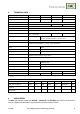
Contents
1 General information .................................................................................................................... 5
2 Declaration of conformity .......................................................................................................... 5
3 Safety instructions ...................................................................................................................... 6
4 Warranty ...................................................................................................................................... 6
5 Used terms and signal indications ............................................................................................ 7
6 Introduction ................................................................................................................................. 7
7 Serial numbers ............................................................................................................................ 8
8 Technical Data ............................................................................................................................. 9
9 Application .................................................................................................................................. 9
10 Description ................................................................................................................................ 10
11 Probe design of the heated version ........................................................................................ 11
11.1 Sample gas connection ...................................................................................................... 11
11.2 Temperature controller ....................................................................................................... 12
11.3 Sample tube and prefilter possibilities ................................................................................ 12
12 Receipt of goods and storage ................................................................................................. 14
13 Preparation for Installation ...................................................................................................... 15
14 Mounting .................................................................................................................................... 16
14.1 Check of the filter element ................................................................................................. 16
14.2 Mounting of the screwed connector at the sample outlet ................................................... 18
14.3 Mounting of probe with sample tube or prefilter ................................................................. 18
14.4 Mounting of sample line ..................................................................................................... 21
14.5 Connection of option test gas feeding or blow back line .................................................... 22
14.6 Connection option pneumatic drive MS1 or MS3 ............................................................... 23
15 Electrical connections .............................................................................................................. 23
15.1 Standard Version with Internal Capillary Tube Thermostat ................................................ 23
15.2 Version with PT100 or thermocouple (option) .................................................................... 24
16 Starting ...................................................................................................................................... 26
16.1 Gas sample probe SP2300-H ............................................................................................ 27
16.2 Option calibration gas feeding and blow back .................................................................... 27
16.2.1 Option check valve /R .................................................................................................. 27
16.2.2 Via 3/2 way ball valve /3VA ......................................................................................... 28
16.3 Option ball valve drives ...................................................................................................... 29
16.3.1 Option Pneumatic drive MS1 or MS3 when using a 2/2-way ball valve /VA ................ 29
16.3.2 Option Pneumatic drive MS1 or MS3 when using a 3/2-way ball valve /3VA .............. 30
16.3.3 Option Electrical ball valve drive .................................................................................. 31
16.4 Option solenoid valve units for blow back, test gas feeding and control of the
pneumatic drives ................................................................................................................ 31
16.4.1 Option drive unit 234B for the solenoid valve units ..................................................... 34
17 Maintenance .............................................................................................................................. 36
17.1 Changing filter element and checking sealings .................................................................. 37
17.2 change of the optional prefilter ........................................................................................... 38
17.3 Change of heating cartridge and thermostat ..................................................................... 38
18 Switching Off ............................................................................................................................. 41
19 Spare part list ............................................................................................................................ 41
20
Connection and mounting data ............................................................................................... 42
21 Appendix .................................................................................................................................... 43