Operating Instructions Gas Sample Probe Series SP® Version SP2000, SP2000-H, SP2300-H, SP2400-H serial number 10283 and higher Gas sampling and gas conditioning technology 2-1.
Contents 1 General information .................................................................................................................... 5 2 Declaration of conformity .......................................................................................................... 5 3 Safety instructions ...................................................................................................................... 6 4 Warranty .......................................................................
List of illustrations Figure 1 Figure 2 Figure 3 Figure 4 Figure 5 Figure 6 Figure 7 Figure 8 Figure 9 Figure 10 Figure 11 Figure 12 Figure 13 Figure 14 Figure 15 Figure 16 Figure 17 Figure 18 Figure 19 Figure 20 Figure 21 Figure 22 Figure 23 Figure 24 Figure 25 Figure 26 Figure 27 Figure 28 Figure 29 Figure 30 Figure 31 Figure 32 2-1.1-ME Design of basic version SP2000-H .................................................................................... 11 Mounting possibilities SP2000...
Dear customer, we have made up this operating manual in such a way that all necessary information about the product can be found and understood quickly and easily. Should you still have any question, please do not hesitate to contact M&C directly or go through your appointed dealer. Respective contact addresses are to be found in the annexe to this operating manual. Please also contact our homepage www.mc-techgroup.com for further information about our products.
Head Office M&C TechGroup Germany GmbH Rehhecke 79 40885 Ratingen Germany Telephone: 02102 / 935 - 0 Fax: 02102 / 935 - 111 E - mail: info@mc-techgroup.com www.mc-techgroup.com 1 GENERAL INFORMATION The product described in this operating manual has been examined before delivery and left our works in perfect condition related to safety regulations. In order to keep this condition and to guarantee a safe operation, it is important to heed the notes and prescriptions made in this operating manual.
3 SAFETY INSTRUCTIONS Please take care of the following basic safety procedures when mounting, starting up or operating this equipment: Read this operating manual before starting up and use of the equipment. The information and warnings given in this operating manual must be heeded. Any work on electrical equipment is only to be carried out by trained specialists as per the regulations currently in force.
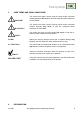
5 USED TERMS AND SIGNAL INDICATIONS DANGER! This means that death, severe physical injuries and/or important material damages will occur in case the respective safety measures are not fulfilled. WARNING! This means that death, severe physical injuries and/or important material damages may occur in case the respective safety measures are not fulfilled. This means that minor physical injuries may occur in case the respective safety measures are not fulfilled.
Major problems of the extractive continuous gas analysis are the materials contained in the sample gas e.g. dust, water vapour and also gas components forming corrosive acids with condensing water vapour. In order to realize an easy-to-maintain measurement the dust has to be separated without condensation of water vapour. This prevents „baking“ of dust and water and the possible acid formation.
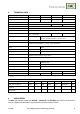
8 TECHNICAL DATA Gas sample probe type SP2000 SP2000-H SP2300-H SP2400-H Part no. 20S1000 20S2000 20S3000 20S3500 Weather protection shield no yes yes yes Protection class terminal box IP54 EN60529 Material filter housing Stainless steel SS316/316Ti* PTFE Titanium Sealing material FPM* /7aT** = PTFE -H320/C** = Graphite Probe flange sealing material Novapress Insitu probe tube / prefilter Optional Sample pressure max. 0,4-6 bar* abs., /7aT**= 2 bar abs., /HP** = 25 bar abs.
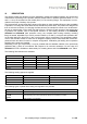
DESCRIPTION The sample probes are designed for easy installation, reliable and flexible operation and trouble-free maintenance. Depending on the problem, different sample tubes or prefilters (see data sheet 2-1.1.0.6 and 2-1.1.0.8) are screwed into the thread (G3/4”) in the mounting flange. This equipment is not included in the scope of delivery of the probe.
PROBE DESIGN OF THE HEATED VERSION A complete gas sample probe consists of the heated filter part and a sample tube or prefilter. The filter housing with its all-round heating element forms a unit with the standard mounting flange DN65 PN6 and the laterally mounted electrical connection box . The heat-insulated shield is mounted on the stainless steel angle sheet which is mounted on the mounting flange. It is secured with 2 pressure clamps.
11.2 TEMPERATURE CONTROLLER In standard version -H, or with option –H320/C temperature control is ensured by way of the capillary tube thermostat which is built into the connection box and which has a regulation range between 0°C to 180°C (-H) or 0°C to 320°C (-H320/C). Rated values can be set to a maximum 180°C resp. 320°C. The temperature has an excess temperature limiter which permanently switches off the heating if the set temperature is exceeded by 30°C.
Type Max. process temperature Length max. Tube ø o. Temperature sensor SP-30H1.1, heating max. 320°C bis max. 550 °C 2,0 m * ø 42,2mm Fe-CuNi SP-30H1.1V, heating max. 320°C bis max. 550 °C 2,0 m * ø 42,2mm Fe-CuNi SP30-H2, heating max. 320°C bis max. 550 °C 2,0 m * ø 42,2mm PT100 SP35-H1.1, heating max. 320°C bis max. 550 °C 0,175 m ø 42,2mm Fe-CuNi SP35-H2, heating max. 320°C bis max.
The following prefilters can be selected : Prefilter Type Part no. Temp. max.
The equipment should be stored in a protected, frost-free room! NOTE! 13 PREPARATION FOR INSTALLATION Select the optimal sampling point in accordance with the generally applicable guidelines or consult the competent persons. Locate the sampling point in such a way that there is adequate space for inserting and removing the probe and pay attention to the insertion length of the probe tube.
Before mounting, the probe must be adjusted to the existing operating conditions. The existing operational parameters are to be checked accordingly prior to commencing mounting work. Low-excess pressure situation mbar bar Process temperature °C, Min. °C Max. Dust loading g/m³ Dust composition – grain size µm Gas composition Parameters to be measured, e.g. O2, CO, SO2, NOX,.., Necessary gas flow corrosive explosive Vol.% mg/Nm³ l/hr, Min. l/hr, Max.
Remove the probe's protection shield after opening the two clamping devices; Turn toggle screw „A“ approx.
14.2 MOUNTING OF THE SCREWED CONNECTOR AT THE SAMPLE OUTLET Remove heat conducting jaws at the sample outlet after loosening the knurled nut . Figure 5 Mounting of screwed connector at sample outlet In order to connect the sample line, screw in a suitably sized threaded connector with a ¼"-NPT connecting thread using PTFE sealing tape. For option second sample outlet SP2000/2x screw in two suitably sized threaded connectors with a ¼"-NPTa.
NOTE! A preferred mounting position is to have the probe with its sample gas outlet pointing downwards, although this is not absolutely necessary for perfect functioning. Insert flange seal (Fig. 6) between sampling flange and probe flange. If the heated probe tube type SP30/35 or the ceramic prefilter type V12 is used, then the probe is to be screwed to their flange (Fig. 6)(with welded threaded bolt). First insert the flange seal between the two flanges.
Figure 6 20 Mounting of sample tube or prefilter Gas sampling and gas conditioning technology 2-1.
14.4 MOUNTING OF SAMPLE LINE Open sample line mounting bracket . Push end of the sample line into silicone cap in the bottom of the angle bracket. Depending on type of heated sample line insert stainless steel pipe end with or without PTFE line through hole in the silicone cap . Figure 7 Mounting of heated sample line Connect stainless steel connection piece or interchangeable PTFE tube at the fitting in the sample gas outlet of the probe.
The temperature-resistant, stainless steel connectors supplied by M&C have a double ferrule system to ensure reliable sealing. After tightening the nuts of these connectors by hand, they should then be tightened exactly 1¼ of a turn using a flat spanner and are then properly mounted. Close mounting bracket .
Optionally, the test gas feeding or back purging can be effected via a check valve -H320/R. The check valve is mounted in the area of the bottom plate. The connecting line (tube/pipe, 6mm outside diameter) can be connected directly on the check valve. After having finished the mountage, put on again the protection cap and fasten it with the quick action locks. 14.
Figure 9 15.2 Electrical connection for SP2000-H, SP2300-H and SP2400-H with thermostat controller VERSION WITH PT100 OR THERMOCOUPLE (OPTION) In case the gas sample probe is ordered with temperature sensor instead of the thermostat, an electronic temperature regulator is necessary, such as the M&C regulator 70304G (Part No. 01B8451). This instrument can be delivered already mounted on the probe and electrically connected, or it is attached to the consignment as separate unit for external mountage.
Figure 10 Electrical connection of external temperature controller e.g. 70304G The electrical connection of the temperature regulator 70304G is effected according to the connection plan (figure 11) and as described in the following: Unscrew and remove the housing lid. Introduce the mains cable (min. 3 x 1,5 mm2, clamping range 6-12mm) through the left cable gland M20x1,5 of the regulator and connect it to the respective terminals.
Figure 11 16 Electrical connection electronic controller 70304G STARTING Before starting up check whether the mains power supply voltage corresponds with the information stated on the probe's nameplate. If there is a built-in ball valve you should also check, if it is closed. In case of hand-operated ball valves, the control grip must be located at the right-hand stop. Switch on mains power supply. Check the rated value setting on the built-in thermostat or on the external controller.
If the rated value temperature needs to be lowered more than 28°C in one step during operation, the thermostat's excess temperature switch-off is triggered! NOTE! When working during operation: W A R N I N G ! High surface temperatures! Touching the surfaces can result in burns. Wear protective gloves and any unauthorized access to the probe must be made impossible ! 16.1 GAS SAMPLE PROBE SP2300-H At the gas sample probe SP2300-H exists the electrical heated filter body from carbon filled PTFE.
This type of calibration gas feeding is not to be used in case of processes with over pressure. A built-in ball valve in the probe entrance is recommended here. Basically, a smaller amount of calibration gas is needed in probes with built-in ball valve as the probe is separated from the system on activating the ball valve and thus there is no danger of mixing with the process gas. In order to close the probe the control grip has to be turned by hand to the right up to the stop.
16.3 OPTION BALL VALVE DRIVES For external control of the probe internal ball valves there is the possibility to use a pneumatic drive with return spring type MS1, MS3 (for 320°C) or an electric drive EA. 16.3.1 OPTION PNEUMATIC DRIVE MS1 OR MS3 WHEN USING A 2/2-WAY BALL VALVE /VA Ball valve open = measuring operation Ball valve closed = e.g. changing filter element at process excess pressure or toxic sample gas or test gas feeding with option check valve /R without loss of test gas into the process.
16.3.2 OPTION PNEUMATIC DRIVE MS1 OR MS3 WHEN USING A 3/2-WAY BALL VALVE /3VA 1. Measuring and blow back MS-B 2. Measuring and test gas feeding MS-C Figure 14 Pneumatischer Antrieb für 3/2-Wege Kugelhahn When placing the order it shall be specified whether the ball valve should be NC, without control air closed resp. switched to test gas feeding or blow back, or NO, without control air open and hence switched to measuring. Standard = NC 30 Gas sampling and gas conditioning technology 2-1.
16.3.3 OPTION ELECTRICAL BALL VALVE DRIVE The electrical ball valve drives for control of two operating modes are available in three control voltages 230V, 115V or 24V DC. Figure 15 16.4 Electrical connection for electrical ball valve drive OPTION SOLENOID VALVE UNITS FOR BLOW BACK, TEST GAS FEEDING AND CONTROL OF THE PNEUMATIC DRIVES All solenoid valve units contain a 3/2-way solenoid valve for control of the pneumatic drive.
Figure 16 Connections solenoid valve unit 2 Solenoid valve unit 3 With 3 solenoid valves for control of 2 operating conditions: 1 x 3/2-way solenoid valve for switching over from measuring operation to back purging for eg. option /3VA 1 x 2/2-way solenoid valve for feeding of test gas via option /R 1 x 2/2-way solenoid valve for feeding of back purge gas 32 Gas sampling and gas conditioning technology 2-1.
Figure 17 2-1.
16.4.1 OPTION DRIVE UNIT 234B FOR THE SOLENOID VALVE UNITS The drive unit 234B is used for control of the solenoid valves in the solenoid valve units for a clocked back purging. The unit is mounted on a cap rail inside a GFK protection housing of the solenoid valve unit and is delivered electrically connected. 16.4.1.1 Function and adjustment of the clock generator K3 The control of the back purge action is made via the electronic clock generator K3 (Typ CT-MXS.
16.4.1.3 Function and adjustment of the time delay relay K1 After the back purge action, the time relay K1 (EZ12AV) finishes the message „Back purge“ with a time delay of eg. 1min and releases the measurement again in order to have sample gas in the analysers when you switch over from back purging to measuring. In the front of the time relay, the switches for the time basis T and the multiplicator xT are situated. Example: Delay time: 1min. Adjust the time basis T to 1 min.
Figure 18 17 Wiring plan of control unit 234B MAINTENANCE The safety instructions specific to the plant and process are to be consulted prior to any maintenance work ! It is difficult to give any recommendations as to a particular maintenance cycle. Depending on your process conditions, a meaningful maintenance cycle must be elaborated for the specific application.
When working during operation: W A R N I N G ! High surface temperatures! Touching the surfaces can result in burns. Wear protective gloves and any unauthorized access to the probe must be made impossible ! 17.1 CHANGING FILTER ELEMENT AND CHECKING SEALINGS Close ball valve (if fitted). Flush probe in case of toxic gases! Remove probe protection shield after opening pressure clamps. Remove filter holder with lid as described in chapter 14.1.
Replace protection shield. Open (if available) ball valve. In order to change prefilters, the entire probe unit must be removed from the process. The prefilters can be cleaned to an extent depending on the manner of soiling mechanicaly or in a ultra sonic bath and can used again. NOTE! 17.2 Prior to carrying out maintenance work on electrical parts, mains voltage should be disconnected from all poles! This also applies to any external control circuits which may be connected.
Heating cartridge Thermostat Figure 20 Position of Thermostat and heating cartridge Unscrew the two hexagon head cap screws A (figure 21) in the back board of the connection box with which this one is mounted to the retaining plate.
Figure 22 Dismounted electrical connection box with heating cartridge and thermostat sensor Loosen the cable gland C (figure 21) for the heating cartridge and the capillary tubes of the thermostat. Disconnect the electrical connection lines of the heating cartridge and the termostat from the terminal block (figure 9). Take off the turning knob from the thermostat. Remove the 2 locking screws D (figure 23) beneath. Take off the locking screws E (figure 23) of the thermostat retaining plate.
18 CARE! 19 SWITCHING OFF Before switching off, i.e. switching off the heating, the gas flow via probe has to be stopped and the probe has to be flushed with inert gas or air in order to avoid condensation of aggressive components from the process gas. SPARE PART LIST Wear, tear and replacement part requirements depend on specific operating conditions. The recommended quantities are based on experience and are not binding.
20 CONNECTION AND MOUNTING DATA Gas sample probe type SP2000 SP2000-H SP2300-H SP2400-H Dimensions B x H x T 340 x 260 x 345 Material filter housing SS316Ti* Sealing materials FPM* /7aT** = PTFE /H320** = Graphite PTFE-Ko Titanium Material probe flange gasket Novapress Electrical connection Switching capacity: 250V, 3A~, 0,25A=, switching point: ∆T 30°C 1 x ¼“NPTi* for tube connection 6, 8 or 10mm**, /H320** = 6mm* or 8mm** ¼“NPTi*, /R** and H320** = tube 6mm 230V 50/60Hz, 800W, /115V*
21 APPENDIX Dimensions / construction, drawing no. : 22551010, 22551020 Sampling possibilities, drawing no. : 22551040, 22091024 Ball valve options and test gas feeding / blow back, drawing no. : 22551110 3/2-way ball valve and pneumatic drive, drawing no. : 2255/05/0/02.98 3/2-way ball valve and pneumatic drive, drawing no. : 2255/05/1/02.98 3/2-way ball valve and pneumatic drive, drawing no. : 2255/05/2/02.98 3/2-way ball valve and pneumatic drive, drawing no. : 2255/05/3/02.
Figure 24 44 SP2000-H basic version Gas sampling and gas conditioning technology 2-1.
Figure 25 2-1.
Figure 26 46 High temperature tube aluminium oxide AO Gas sampling and gas conditioning technology 2-1.
Figure 27 2-1.1-ME Heated sample tubes SP30-H...
Gas sampling and gas conditioning technology 2-1.
Figure 28 2-1.
Figure 29 50 SP2000-H/3VA/MS-NC-B Gas sampling and gas conditioning technology 2-1.
Figure 30 2-1.
Figure 31 52 SP2000-H/3VA/MS-NO-B Gas sampling and gas conditioning technology 2-1.
Figure 32 2-1.