
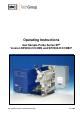
Operator's manual

2
Gas sampling and gas conditioning technology 2-1.1.6-ME
Contents
1 General information .................................................................................................................... 4
2 Declaration of conformity ........................................................................................................... 4
3 Safety instructions ...................................................................................................................... 5
4 Warranty ....................................................................................................................................... 5
5 Used terms and signal indications ............................................................................................ 6
6 Introduction ................................................................................................................................. 7
6.1 Serial numbers ........................................................................................................................ 7
6.2 Power supply .......................................................................................................................... 7
7 Technical Data ............................................................................................................................. 8
8 Applications ................................................................................................................................. 8
9 Description ................................................................................................................................... 9
9.1 Probe Structure ..................................................................................................................... 10
10 Receipt of goods and storage ............................................................................................... 12
11 Preparation and Installation .................................................................................................. 12
12 Mounting ................................................................................................................................. 13
12.1 Pneumatic connexions ...................................................................................................... 14
12.2 New filter housing lid from Serial Nos. 10283 .................................................................... 15
13 Electrical connections ........................................................................................................... 16
13.1 Standard Version with Internal Capillary Tube Thermostat ............................................... 17
13.2 Version with External Temperature Control ....................................................................... 18
14 Starting .................................................................................................................................... 18
14.1 Calibration gas feed and backflushing ............................................................................... 19
15 Maintenance ........................................................................................................................... 20
16 Switching Off .......................................................................................................................... 20
17 Spare parts list ....................................................................................................................... 21
18 Appendix ................................................................................................................................. 22
List of illustrations
Figure 1 Probe mounting with adapter flange or R2” adapter ........................................................ 13
Figure 2 Connexions SP2200-H/C/I/BB and SP2200-H/C/I/BB/F .................................................. 14
Figure 3 New filter housing lid ex serial number 10283 .................................................................. 15
Figure 4 Removing the new filter housing lid .................................................................................. 16
Figure 5 Electrical connection at the capillary tube thermostat ...................................................... 17
Figure 6 Electrical connexions at the electronic controller 70304G ................................................ 18
Figure 7 Electrical connexions for SP2200-H.. with thermostate controller .................................... 23
Figure 8 Electrical connexions for SP2200-H.. with electronic controller 70304G ......................... 24
Figure 9 Possible filter elements .................................................................................................... 25
Figure 10 Sample tubes and pre filter .............................................................................................. 26
Figure 11 High temperature sample tube out of aluminium oxide .................................................... 27
Figure 12 Heated sample tubes SP30.. ............................................................................................ 28
Figure 13 Solenoid valve unit 2 ........................................................................................................ 29