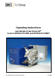
Operating Instructions Gas Sample Probe Series SP® Version SP2200-H/C/I/BB und SP2200-H/C/I/BB/F Gas sampling and gas conditioning technology 2-1.1.
Contents 1 2 3 4 5 6 General information .................................................................................................................... 4 Declaration of conformity ........................................................................................................... 4 Safety instructions ...................................................................................................................... 5 Warranty ..............................................................
Dear customer, we have made up this operating manual in such a way that all necessary information about the product can be found and understood quickly and easily. Should you still have any question, please do not hesitate to contact M&C directly or go through your appointed dealer. Respective contact addresses are to be found in the annexe to this operating manual. Please also contact our homepage www.mc-techgroup.com for further information about our products.
Head Office M&C TechGroup Germany GmbH Rehhecke 79 40885 Ratingen Germany Telephone: 02102 / 935 - 0 Fax: 02102 / 935 - 111 E - mail: info@mc-techgroup.com www.mc-techgroup.com 1 GENERAL INFORMATION The product described in this operating manual has been examined before delivery and left our works in perfect condition related to safety regulations. In order to keep this condition and to guarantee a safe operation, it is important to heed the notes and prescriptions made in this operating manual.
3 SAFETY INSTRUCTIONS Please take care of the following basic safety procedures when mounting, starting up or operating this equipment: Read this operating manual before starting up and use of the equipment. The information and warnings given in this operating manual must be heeded. Any work on electrical equipment is only to be carried out by trained specialists as per the regulations currently in force.
5 USED TERMS AND SIGNAL INDICATIONS This means that death, severe physical injuries and/or important material damages will occur in case the respective safety measures are not fulfilled. DANGER! This means that death, severe physical injuries and/or important material damages may occur in case the respective safety measures are not fulfilled. WARNING! This means that minor physical injuries may occur in case the respective safety measures are not fulfilled.
6 INTRODUCTION M&C gas sample probes provide direct insitu ultra-fine filtration during continuous gas sampling for analytic measurements. In this way, part of the necessary maintenance work for a system is concentrated on a single point. This filter technology has the major advantage that dust mixtures consisting of ultra-fine and coarse dusts can be optimally retained with the least possible maintenance work.
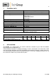
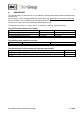
7 TECHNICAL DATA Mains supply Electrical connection 230V 50/60Hz 800W*, optional 115V 60Hz 800W terminals; max 4mm², 2x PG13,5 cable gland Protective type Ambient temperature IP54 (EN 60529)* thermostat: -20°C to 60°C PT100, thermocouple: -20°C to 80°C 0-180°C* after 2 hours 30°C to TSet* 250V 3A AC, 0,25A DC 1/4"-NPT i., for max. 10mm tube connectors tube fitting 8mm ø tube 6mm ø 120 ml 0,4 to 6 bar abs.
9 DESCRIPTION The sample probes are designed for easy installation, reliable and flexible operation and trouble-free maintenance. Filter elements can be changed without the need for tools and without disconnecting the sample line, the filter chamber can be cleaned easily, the probe tube can be cleaned without removing the probe: these are just a few of the many advantages offered by this probe. The filter element, which has a large surface, is located in a stainless steel filter housing.
9.1 PROBE STRUCTURE The filter housing with its all-round heating element forms a unit with the standard mounting flange DN65 PN6 and the laterally mounted electrical connection box. The heat-insulated shield is mounted on the stainless steel angle sheet which is mounted on the mounting flange. It is secured with 2 pressure clamps. The cover ensures a uniform distribution of heat over the probe heater and at the same time serves as protection against weather and accidental contact.
Depending on the process gas temperature and composition, probe tubes materials are used with ¾" connections: Material Type Process temperature max. length Stainless steel 316 up to max. 600 °C 2,5 m SS Titan up to max. 400 °C Ti 2,5 m * Hastelloy up to max. 900 °C Ha 2,5 m * Incolloy 956 up to max. 1200 °C In 2,0 m * Kanthal up to max. 1300 °C Ka 2,5 m * Alu. oxide up to max. 1800 °C AO 1,5 m * PVDF up to max. 90 °C PV 1,5 m * PTFE up to max. 160 °C 0,5 m T made of different Pipe (nipple) o.d.
10 RECEIPT OF GOODS AND STORAGE The gas sample probe and any special accessories should be removed carefully from the packaging and checked immediately for completeness against the delivery note. Check the goods for any damage incurred during transport and if necessary inform your transport insurer of any damage. The gas sample probe is normally delivered in two packaging units: 1. The gas sample probe with the screws, nuts and flange seal required for mounting. 2.
12 MOUNTING M&C SP2200.. probes are designed for stationary use and if properly selected and mounted a long service life and minimum maintenance are guaranteed. Remove the probe's protection shield after opening the two clamping devices. Turn the U-bolt at the front end of the filter receptacle several times to the left until the retaining bolt can also be turned sideways to the left. Remove the filter receptacle from the probe and check whether the filter element is screwed on tightly.
Now insert the process-internal probe section of the complete probe unit into the probe connection, but first attach the flange seal to the probe connection and screw using the screws and nuts supplied. NOTE! 12.1 A preferred mounting position is to have the probe with its sample gas outlet pointing downwards, although this is not absolutely necessary for perfect functioning. An advantage as well is mounting the probe with an angle (10°) downwards.
12.2 NEW FILTER HOUSING LID FROM SERIAL NOS. 10283 The sample probe series SP2000 will be delivered, starting with the serial number 10283, with a new filter housing lid lock, to make filter replacement easier. The modification consists of a toggle screw „A“, which allows to fasten the filter housing lid by turning the screw clockwise and lifting up the lid by turning it anti-clockwise. After turning the clamp „B“ to the left hand side, the filter housing lid can be removed.
The following pictures should explain the above mentioned steps. Figure 4 Removing the new filter housing lid The new locking is available as a complete set for sample probes older than serial number 10283 (part no.: 93 S 0081). 13 ELECTRICAL CONNECTIONS WARNING! WARNING! When connecting the equipment, please ensure that the supply voltage is identical with the information provided on the model type plate. Use always the low temperature alarm.
NOTE! Attention must be paid to the requirements of IEC 364 (DIN VDE 0100) when setting high-power electrical units with nominal voltages of up to 1000 V, together with the associated standards and stipulations. In any case we recommend the use of temperature resistant cable ! A main switch and matching fuse must be provided externally! The main circuit must be equipped with a fuse corresponding to the nominal current (over current protection); for electrical details see technical data. 13.
13.2 VERSION WITH EXTERNAL TEMPERATURE CONTROL Remove the lid of the connection box. The electrical connection layout is located in the lid. Insert the mains cable coming from the external temperature controller (min. 3 x 1.5 mm²) through the threaded cable gland and connect to the appropriate terminals. Insert the temperature sensor cable through the threaded cable gland and connect to the appropriate terminals. Screw lid back on.
If the rated value temperature needs to be lowered more than 30°C in one step during operation, the thermostat's excess temperature switch-off is triggered! NOTE! WARNING! 14.1 Be careful when you get in contact with the probe’s surface during operation. The high surface temperatures may cause burnings.
15 MAINTENANCE The safety instructions specific to the plant and process are to be consulted prior to any maintenance work! It is difficult to give any recommendations as to a particular maintenance cycle. Depending on your process conditions, a meaningful maintenance cycle must be elaborated for the specific application. An indication that probe-maintenance may be necessary could be shown by a constant decline in the amount of sample gas in the analysis system.
17 SPARE PARTS LIST Wear, tear and replacement part requirements depend on specific operating conditions. The recommended quantities are based on experience and they are not binding. Gas sample probe SP2200-H.. (C) Consumable parts (R) Recommended spare parts (S) Spare parts Recommended quantity being in operation [years] Part No.
18 APPENDIX Electrical plans Filter elements – spare parts Sample tubes and pre filters Solenoid unit 2 More product documentation is available on our Internet catalogue: www.mc-techgroup.com Sample tubes series SP Document: 2-1.1.0.6 Prefilter series SP Document: 2-1.1.0.8 Gas sampling and gas conditioning technology 2-1.1.
Figure 7 Electrical connexions for SP2200-H.. with thermostate controller Gas sampling and gas conditioning technology 2-1.1.
Figure 8 Electrical connexions for SP2200-H.. with electronic controller 70304G Gas sampling and gas conditioning technology 2-1.1.
Figure 9 Possible filter elements Gas sampling and gas conditioning technology 2-1.1.
Figure 10 Sample tubes and pre filter Gas sampling and gas conditioning technology 2-1.1.
Figure 11 High temperature sample tube out of aluminium oxide Gas sampling and gas conditioning technology 2-1.1.
Figure 12 Heated sample tubes SP30.. Gas sampling and gas conditioning technology 2-1.1.
Figure 13 Solenoid valve unit 2 Gas sampling and gas conditioning technology 2-1.1.