
User Manual

M&C TechGroup Germany GmbH • Rehhecke 79 • 40885 Ratingen • Germany
info@mc-techgroup.com • www.mc-techgroup.com • Fon +49 2102 935-0 • Fax +49 2102 935-111
2.3
Technical Data
Technical specications and illustrations are without
obligation, subject to modications. 10.04/06.06
For further technical informations see data sheet 2-1.1 standard probe SP2000-H.
SP2200-H/C/I/BB SP2200-H/C/I/BB/F
Part Number 20S2010 20S2015
Operating temperature max. 180 °C
Power supply 230V 50Hz, 800W optional 115V 60Hz
Calibration gas valve /C Check valve, cracking pressure: >0,7 bar g
Isolation valve /I Bellow valve with pneum. actuator, control pressure: 3-10 bar g connection: 1/8"NPT i
Blow back valves /BB+/BB/F High flow rate check valve, cracking pressure: >0,7 bar g, recommended: 3-6 bar g
we recommend short pressure pushes to avoid decreasing of temperature in blow back area.
Connection: tube connector 8 mm o.d.
Flange material: stainless steel 316Ti, dimensions: DN65 PN6 B
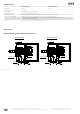
Dimensions
Electrically heated gas sample probe series SP
®
(P 3-10bar)
1/4"NPT
(P >0,7bar)
1/8"NPT1/8"NPT
(P 3-10bar)(P >0,7bar)
1/4"NPT
SP2200-H/C/I/BB/F
Check valve
Isolation valve
Check valve
Tube DN6/8
Blow back in
Sample out
Flange DN65 PN6
Tube DN4/6
Cal.-gas in
Control in
Check valve
SP2200-H/C/I/BB
Control in
Sample out
Tube DN6/8
Blow back in
Isolation valve
Flange DN65 PN6
Cal.-gas in
Tube DN4/6
Check valve
Dimensions in mm