OPERATING INSTRUCTIONS Gas Sample Probe Serie SP2100-H Gas sampling and gas conditioning technology 3-3.
Dear customer, we have made up this operating manual in such a way that all necessary information about the product can be found and understood quickly and easily. Should you still have any question, please do not hesitate to contact M&C directly or go through your appointed dealer. Respective contact addresses are to be found in the annexe to this operating manual. Please also contact our homepage www.mc-techgroup.com for further information about our products.
Content 1 2 3 4 5 6 General information...................................................................................................................... 4 Declaration of conformity ............................................................................................................ 4 Safety instructions ....................................................................................................................... 5 Warranty ............................................................
Head Office M&C TechGroup Germany GmbH Rehhecke 79 40885 Ratingen Germany Telephone: 02102 / 935 - 0 Fax: 02102 / 935 - 111 E - mail: info@mc-techgroup.com www.mc-techgroup.com 1 GENERAL INFORMATION The product described in this operating manual has been examined before delivery and left our works in perfect condition related to safety regulations.
3 SAFETY INSTRUCTIONS Please take care of the following basic safety procedures when mounting, starting up or operating this equipment: Read this operating manual before starting up and use of the equipment. The information and warnings given in this operating manual must be heeded. Any work on electrical equipment is only to be carried out by trained specialists as per the regulations currently in force.
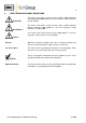
5 USED TERMS AND SIGNAL INDICATIONS DANGER! This means that death, severe physical injuries and/or important material damages will occur in case the respective safety measures are not fulfilled. WARNING! This means that death, severe physical injuries and/or important material damages may occur in case the respective safety measures are not fulfilled. This means that minor physical injuries may occur in case the respective safety measures are not fulfilled.
6 INTRODUCTION M&C gas sample probes provide direct insitu ultra-fine filtration during continuous gas sampling for analytic measurements. In this way, part of the necessary maintenance work for a system is concentrated on a single point. This filter technology has the major advantage that dust mixtures consisting of ultra-fine and coarse dusts can be optimally retained with the least possible maintenance work.
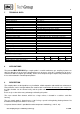
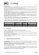
7 TECHNICAL DATA Probe series SP® Part No.
Probe Structure: The filter housing with its all-round heating element forms a unit with the standard mounting flange DN65 PN6 and the laterally mounted electrical connection socket. Mounting jaws are located at the aperture on the underside of the outer protective casing. These have an integrated silicon cap for the connection of heated M&C sampling tubes with external diameters of 40 mm to a max. 55 mm.
If the ambient temperature in the area of the connections is >80°C as a result of radiated heat, then a radiated-heat deflector must be mounted to protect the probe. The connection's mounting flange connection should comply with DN65 PN6. If other connection sizes are required, a special adapter flange /S010 can be supplied as an option. Before mounting, the probe must be adjusted to the existing operating conditions.
Connection of the heated sample line: Remove the heat-conducting shoes at the sample gas outlet after loosening the knurled-head screw. In order to connect the sample line, screw in a suitably sized threaded connector with a ¼"NPT connecting thread using PTFE sealing tape. Make sure that the connection is leakproof ! NOTE! Push the silicon cap onto the end of the heated sampling tube and introduce the tube connection piece into the bolted pipe joint and connect.
13 ELECTRICAL CONNECTION WARNING! NOTE! When connecting the equipment, please ensure that the supply voltage is identical with the information provided on the model type plate. Attention must be paid to the requirements of IEC 364 (DIN VDE 0100) when setting high-power electrical units with nominal voltages of up to 1000 V, together with the associated standards and stipulations.
14 STARTING UP Before starting up check whether the mains power supply voltage corresponds with the information stated on the probe's nameplate. Switch on mains power supply. The total heating-up time is approximately 2 hours. After about 1 hour the probe is already sufficiently heated for the temperature to have exceeded the temperature failure alarm value (160°C), but it still takes about another hour until operating temperature is reached.
Figure 2 16 Replacing the filter element SWITCHING OFF Before switching off, i.e. switching off the heating, the probe be flushed with inert gas or air in order to avoid condensation of aggressive components from the process gas. Gas sampling and gas conditioning technology 2-1.
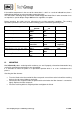
17 SPARE PARTS LIST Wear, tear and replacement part requirements depend on specific operating conditions. The recommended quantities are based on experience and they are not binding. Gas sample probe SP2100-H (C) Consumable parts (R) Recommended spare parts (S) Spare parts Part No.
Figure 3 Dimensions and mechanical construction SP2100-H Gas sampling and gas conditioning technology 2-1.