OPERATING INSTRUCTIONS Gas Sample Probe SP® SP210-H and SP210-H/W Gas sampling and gas conditioning technology 2-1.0.
Dear customer, we have made up this operating manual in such a way that all necessary information about the product can be found and understood quickly and easily. Should you still have any question, please do not hesitate to contact M&C directly or go through your appointed dealer. Respective contact addresses are to be found in the annexe to this operating manual. Please also contact our homepage www.mc-techgroup.com for further information about our products.
Content 1 2 3 4 5 6 General information....................................................................................................................... 4 Declaration of conformity ............................................................................................................. 4 Safety instructions ........................................................................................................................ 5 Warranty .........................................................
Head Office M&C TechGroup Germany GmbH Rehhecke 79 40885 Ratingen Germany Telephone: 02102 / 935 - 0 Fax: 02102 / 935 - 111 E - mail: info@mc-techgroup.com www.mc-techgroup.com 1 GENERAL INFORMATION The product described in this operating manual has been examined before delivery and left our works in perfect condition related to safety regulations.
3 SAFETY INSTRUCTIONS Please take care of the following basic safety procedures when mounting, starting up or operating this equipment: Read this operating manual before starting up and use of the equipment. The information and warnings given in this operating manual must be heeded. Any work on electrical equipment is only to be carried out by trained specialists as per the regulations currently in force.
5 USED TERMS AND SIGNAL INDICATIONS DANGER! This means that death, severe physical injuries and/or important material damages will occur in case the respective safety measures are not fulfilled. WARNING! This means that death, severe physical injuries and/or important material damages may occur in case the respective safety measures are not fulfilled. This means that minor physical injuries may occur in case the respective safety measures are not fulfilled.
6 INTRODUCTION M&C gas sample probes provide direct insitu ultra-fine filtration during continuous gas sampling for analytic measurements. In this way, part of the necessary maintenance work for a system is concentrated on a single point. This filter technology has the major advantage that dust mixtures consisting of ultra-fine and coarse dusts can be optimally retained with the least possible maintenance work.
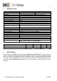
7 TECHNICAL DATA Gas Sample Probe Series SP® Part No.
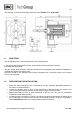
9 DESCRIPTION The sample probes are designed for easy installation, reliable operation and trouble-free maintenance.
The following cross-sectional drawing shows the probe SP210-H resp. SP210-H/W. Figure 1 11 Dimensions SP210-H/W RECEPTION The gas sample probe is normally delivered in two packaging units: 1. The gas sample probe with the screws, nuts and flange seal required for mounting. 2. Sample tube with gasket. The gas sample probe should be removed carefully from the packaging and checked immediately for completeness against the delivery note.
• • • If the ambient temperature in the area of the connections is >80°C as a result of radiated heat, then a radiated-heat deflector must be mounted to protect the probe. The connection's mounting flange connection should comply with DN65 PN6. If other connection sizes are required, a special adapter flange /S010 can be supplied as an option. Before mounting, the probe must be adjusted to the existing operating conditions.
Make sure that the connection is leakproof ! NOTE! • Now place the red silicon heat insulation around the connection. Mounting of sample tube and adapter flange: • • • • • Screw either the probe tube directly into the ¾" inner thread in the flange of the probe with the ¾" flat gasket and tighten. If the heated probe tube type SP30/35 is used then the probe is to be screwed to their flange (with welded threaded bolt). First insert the flange seal between the two flanges.
14 EL LECTRICA AL CONNE ECTION WARNING! NOTE! Wh hen connecting the equipmentt, please e ensure tha at the sup pply volltage is ide entical with h the inform mation prov vided on th he model ty ype pla ate. Atttention mu ust be paid d to the re equirementts of IEC 364 3 (DIN VDE V 010 00) when setting high-powe h r electrica al units with w nomiinal volltages of up u to 1000 0 V, together with the e associatted standards and d stipulatio ons.
15 START TING UP Befo ore starting up check whether the e mains po ower supply y voltage co orresponds with the in nformation state ed on the probe's name eplate. • Switch on o mains po ower supplyy. The total heating-up p time is approximatelyy 2 hours. After A about 1 hour the probe is already sufficientlyy heated fo or the temp perature to have exce eeded the tempera ature failure e alarm value (160°C)), but it still takes abo out anotherr hour until operating tempera ature is reacched.
• O-Ring k is only for guidance of the probe lid and has no sealing function. The rebuilding has to be done in the reverse order. Figure 3 17 Replacing the filter element SWITCHING OFF Before switching off, i.e. switching off the heating, the probe be flushed with inert gas or air in order to avoid condensation of aggressive components from the process gas. Gas sampling and gas conditioning technology 2-1.0.
18 SPARE PARTS LIST Wear, tear and replacement part requirements depend on specific operating conditions. The recommended quantities are based on experience and they are not binding. Gas sample probe SP210-H, SP210-H/W (C) Consumable parts (R) Recommended spare parts (S) Spare parts Part No.