
Operator's manual Owner manual

4
Gas sampling and gas conditioning technology 2-1.1.7.2-ME
List of illustrations
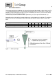
Figure 1 Dilution principle ................................................................................................................. 9
Figure 2 SP2006-H/DIL resp. SP2006-H280/DIL ........................................................................... 12
Figure 3 SP2006-H/DIL-BR-VA (-MS1) .......................................................................................... 12
Figure 4 SP2006-H/DIL-BR ............................................................................................................ 12
Figure 5 SP2006-H/DIL-B .............................................................................................................. 13
Figure 6 SP2006-H/DIL-BR-I ......................................................................................................... 13
Figure 7 Control panel -S or -S1 .................................................................................................... 13
Figure 8 Construction and dimensions of the SP2006- ........................................................... 15
Figure 9 Dimensions control panel -S or -S1 ................................................................................. 15
Figure 10 Schematic drawing of the filter housing cover ................................................................. 16
Figure 11 Dismounting of the filter housing cover ............................................................................ 17
Figure 12 Connection of supply and sample lines ........................................................................... 18
Figure 13 Electrical connection for SP2006-H.. at the 70304G ....................................................... 21
Figure 14 Extract from an injector data sheet .................................................................................. 23
Figure 15 Suction flow at 0,9 or 1bar abs. in dependence on the bypass gas pressure ................. 23
Figure 16 Drawing of the dilution and bypass block ......................................................................... 26
Figure 17 Dilution block with critical orifice, eductor, O-ring seals and tool ..................................... 27
Figure 18 Bypass block with eductor and O-ring seals .................................................................... 28
Figure 19 Eductor and o-rings .......................................................................................................... 29
Figure 20 Critical orifice and o-rings ................................................................................................ 29