
Operator's manual Owner manual

20
Gas sampling and gas conditioning technology 2-1.1.7.2-ME
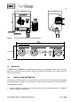
14.5 CONNECTION OF THE VACUUM GAUGE
NOTE!
When using the 19” control panels –S or –S1, the connection of the vacuum
gauge is possible. Otherwise the connection is closed by a blind cap.
Fo
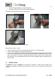
Open the diagonal FRP-housing
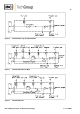
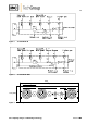
Mount the hose pipe or tube to the respective fitting (see drawings in the annex)
Close the diagonal FRP-housing
panels –S or –S1 corresponding marked connectors for the vacuum gauge are pro-
vided at the rear of the unit.
14.6 ELECTRICAL CONNECTION
The temperature setting of the dilution probe SP2006-H… is made on the electronic controller e.g.
70304G.
W A R N I N G !
The incorrect mains voltage can destroy the unit. Check the type
plate for the correct voltage prior to connection!
The dilution probe must be mounted in such a way that touching
the live parts is excluded!
In any case, we recommend the use of temperature resistant ca-
bles!
The alarm contact for low temperature must be controlled!
In case of a low temperature alarm (failure of heating or sensor) the
dilution gas or bypass gas supply must be interrupted to avoid se-
rious damage of the dilution probe. We recommend to switch the
low temperature alarm on to external solenoid valves that provide
the above mentioned function!
NOTE!
For the erection of power installations with nominal voltages of up
to 1000V, the requirements of VDE 0100 and its associated stan-
dards and specifications must be observed.
A mains switch must be provided externally.
The supply circuit of the unit must be equipped with a fuse with the
correct rating (over current protection); the electrical details see
technical data.
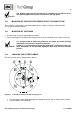
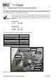
Remove cover of the controller 70304G.
Insert the mains cable (min. 3 x 1,5 mm
2
) through the cable gland and connect to the appropri-
ate terminals (1 = ground, 2 = N, 4 = L).
Insert the signal cable (low temperature alarm) through the cable gland and connect to the ap-
propriate terminals 11 and 12 (contact position T
u
shows alarm event).
Screw cover back in place.