
Operator's manual Owner manual

18
Gas sampling and gas conditioning technology 2-1.1.7.2-ME
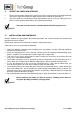
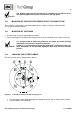
14.1 CONNECTION OF THE SUPPLY AND SAMPLE LINES
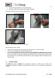
All pneumatic lines have to be inserted through the CES cable entry, size 5, with an operative range of
36 70mm. It is located in the bottom of the FRP-housing. After insertion and connection of all lines
the CES cable entry can be shrinked by an air heater.
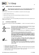
NOTE!
Increases of pressure due to use of long sample gas lines at the outlet may have a
great influence on the measuring result. For this reason, we recommend the fol-
lowing nominal widths and lengths for the sample lines in dependence on the type
of injector:
Injector type I:
i
max. 50m
i
max. 150m
Injector type II:
i
8mm max. 15m
i
10mm max. 40m
i
12mm max. 80m
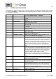
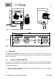
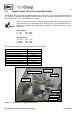
The connections for the supply and sample lines are as follows:
Connection
Dimension
Testgas In
Dilution gas In
Low pressure manometer
Tub
Sample gas Out (diluted)
Bypass gas In
Bypass gas Out (diluted)
Sample gas Out (undiluted)
Blow back In
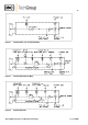
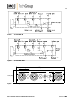
Figure 12 Connection of supply and sample lines
Low pressure
manometer
Sample OUT diluted
Sample OUT
not diluted
Test gas IN
Blow back IN
Dilution gas IN
Bypass gas IN