Operating Manual Series SP® Version SP2006-H/DIL... and SP2006-H280/DIL… Gas sampling and gas conditioning technology 2-1.1.7.
Dear customer, we have made up this operating manual in such a way that all necessary information about the product can be found and understood quickly and easily. Should you still have any question, please do not hesitate to contact M&C directly or go through your appointed dealer. Respective contact addresses are to be found in the annexe to this operating manual. Please also contact our homepage www.mc-techgroup.com for further information about our products.
Contents 1 2 3 4 5 6 General information.................................................................................................................... 5 Declaration of conformity .......................................................................................................... 5 Safety instructions ..................................................................................................................... 6 Warranty .................................................................
List of illustrations Figure 1 Figure 2 Figure 3 Figure 4 Figure 5 Figure 6 Figure 7 Figure 8 Figure 9 Figure 10 Figure 11 Figure 12 Figure 13 Figure 14 Figure 15 Figure 16 Figure 17 Figure 18 Figure 19 Figure 20 Dilution principle................................................................................................................. 9 SP2006-H/DIL resp. SP2006-H280/DIL ........................................................................... 12 SP2006-H/DIL-BR-VA (-MS1) .....................
Head Office M&C TechGroup Germany GmbH Rehhecke 79 40885 Ratingen Germany Telephone: 02102 / 935 - 0 Fax: 02102 / 935 - 111 E - mail: info@mc-techgroup.com www.mc-techgroup.com 1 GENERAL INFORMATION The product described in this operating manual has been examined before delivery and left our works in perfect condition related to safety regulations. In order to keep this condition and to guarantee a safe operation, it is important to heed the notes and prescriptions made in this operating manual.
3 SAFETY INSTRUCTIONS Please take care of the following basic safety procedures when mounting, starting up or operating this equipment: Read this operating manual before starting up and use of the equipment. The information and warnings given in this operating manual must be heeded. Any work on electrical equipment is only to be carried out by trained specialists as per the regulations currently in force.
5 USED TERMS AND SIGNAL INDICATIONS DANGER! This means that death, severe physical injuries and/or important material damages will occur in case the respective safety measures are not fulfilled. WARNING! This means that death, severe physical injuries and/or important material damages may occur in case the respective safety measures are not fulfilled. This means that minor physical injuries may occur in case the respective safety measures are not fulfilled.
6 INTRODUCTION The M&C gas sample probes type SP2006-H.. are based on the patented probe SP2000-H and are used for continuous gas sampling and dilution. 6.1 SERIAL NUMBER The type plates are to be found where the electrical connection box is placed. NOTE! 7 Please indicate the serial number of the equipment in case of any question and when ordering spare parts.
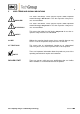
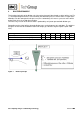
9 DILUTION PRINCIPLE The functional principle of the dilution unit is based on ultrasonic flow through a critical orifice (see Fig. 1). The flow through the orifice is constant when the differential pressure via the orifice is higher than 500 mbar. For the atmospheric inlet pressure (Pin = 1020 mbar), this means a pressure at the orifice outlet (Pout) of less than 520 mbar absolute. The necessary vacuum at the orifice outlet is produced by an injector operated with dilution gas.
10 DESCRIPTION The dilution unit including the critical orifice is mounted directly at the probe body and therefore heated up with the probe to a stable temperature. The incorporated pre-heater heats up the dilution gas to the probe temperature. Both steps avoid that sample gas decreases under the dewpoint. Calibration gas enters the probe via an integrated connection. The probe can be heated up to 180 °C or 280 °C. As an option a heated manual operated 2 way ball valve is available.
10.1 OPTIONS AND VARIATIONS The following list shows the probe types and options available. The diversity of options and the modular design of the M&C gas sample probes ensure optimum probe selection to suit the particular process and ambient conditions. Part No. 20 S 4423 (a) 20 S 4424 (a) 20S 9401 20 S 9403 20 S 9408 20 S 4250 20 S 4260 Type M&C gas sample dilution probe SP2000H/DIL ....
Figure 2 SP2006-H/DIL resp. SP2006-H280/DIL Figure 3 SP2006-H/DIL-BR-VA (-MS1) Figure 4 SP2006-H/DIL-BR Gas sampling and gas conditioning technology 2-1.1.7.
Figure 5 SP2006-H/DIL-B Figure 6 SP2006-H/DIL-BR-I 482 (84TE) Control panel Option: Bypass Bypass-Injector Dilution gas Test gas open 2,0 132 (3HE) 1,0 0,0 Figure 7 3,0 4,0 5,0 6,0 2,0 3,0 1,0 0,0 4,0 5,0 6,0 Injector Depression open -0,6 -0,8 -1,0 -0,4 -0,2 0,0 Control panel -S or -S1 Gas sampling and gas conditioning technology 2-1.1.7.
11 RECEIPT OF GOODS AND STORAGE Please take the probe and possible special accessories carefully out of the packaging immediately after receipt and compare the goods with the items listed on the packing list. Check the goods for any damage caused during delivery and, if necessary, notify your transport insurance company without delay of any damage discovered.
Figure 8 Construction and dimensions of the SP2006-H… 482 (84TE) Control panel Option: Bypass Bypass-Injector Dilution gas Test gas open 2,0 132 (3HE) 13 4,0 1,0 0,0 Figure 9 3,0 5,0 6,0 2,0 3,0 1,0 0,0 4,0 5,0 6,0 Injector Depression open -0,6 -0,8 -1,0 -0,4 -0,2 0,0 Dimensions control panel -S or -S1 MOUNTING The M&C probes SP2006-H..
The dilution probe must be checked for its suitability for use with the available operating parameters prior to installation (see type plate). NOTE! 13.2 MOUNTING OF THE PREFILTER RESPECTIVELY THE SAMPLE TUBE The pre-filter or sample tube is mounted together with a suitable sealing by screwing into the G ¾“ thread of the probe flange. 13.3 MOUNTING OF THE PROBE Put the flange sealing on the bleeder connection.
Turn the clamp clip B to the left side (direction G); Pull out the filter housing cover with the toggle handle A. The photos shall illustrate the above mentioned steps. Figure 11 Dismounting of the filter housing cover Now, the filter element is visible. 14 Check on the filter pressing screw whether the filter element is screwed on tightly. Push the cover with filter element into the probe again.
14.1 CONNECTION OF THE SUPPLY AND SAMPLE LINES All pneumatic lines have to be inserted through the CES cable entry, size 5, with an operative range of 36 – 70mm. It is located in the bottom of the FRP-housing. After insertion and connection of all lines the CES cable entry can be shrinked by an air heater. NOTE! Increases of pressure due to use of long sample gas lines at the outlet may have a great influence on the measuring result.
14.2 CONNECTION OF SAMPLE LINES All connections for the sample lines are tube connectors out of stainl. steel suitable for connection of stainl. steel tubes or hose pipes with dimension 1/4”. Only the outlet of the diluted sample gas and the blow back inlet is dimensioned for stainl. steel tube or flexible tube of 3/8”. NOTE! When connecting hose pipes to stainl. Steel fittings, a supporting sleeve must always be used. The connection must be checked for tightness.
14.5 CONNECTION OF THE VACUUM GAUGE When using the 19” control panels –S or –S1, the connection of the vacuum gauge is possible. Otherwise the connection is closed by a blind cap. NOTE! For all versions, a tube connector 1/4” is available for connection of the vacuum gauge.
Front view 230V, 50Hz Front view 120V, 60Hz For Reset press EXIT and Option mA-outlet 15 16 3/2 3/1 2/2 2/3 2/4 2/8 2/6 3/8 3/7 3/4 3/5 3/2 3/1 2/2 2/3 2/4 2/8 2/6 3/8 3/7 3/4 3/5 Alternative Connection PT100 1 2 3 4 5 6 7 8 9 10111213 14 Power 230V,50Hz 1 2 3 4 5 6 7 8 9 10111213 14 Alarm contact NO 250V AC, max.3A Heating max. 250V, 50Hz, 15A Thermo couple Fe-CuNi Heating max. 120V, 60Hz, 15A Special cable Figure 13 Alarm contact NO 250V AC, max.
15 INITIAL STARTING Prior to initial use, system and process-specific safety measures must be observed. The relevant safety requirements and procedures for the medium to be sampled must be heeded. WARNING! The supply of gas to the injectors is only allowed when the heated dilution probe has reached its operating temperature (see technical data).
The following table shows an extract from an injector data sheet. Injektortyp Injektor-Nr. I Injector type ..... Injector No. Betriebsdruck Operating pressure [bar] 2,4 2,6 2,8 3,0 3,2 3,4 3,6 3,8 4,0 Durchfluss Flow [l/h] 415 435 460 490 510 535 560 585 605 Für Verdünnungssystem-Nr. ....../............ For dilution system No.
In the event of low temperature (failure of the heating) the supply of dilution gas must be interrupted! WARNING! 15.1 CALIBRATION A calibration of the downstream analyser system or checking the dilution factor must always be effected under operating conditions. Above the test gas valve, an appropriate test gas can be feeded. NOTE! The test gas pressure has to be higher than 0,7 bar, because the pressure control valve has an opening pressure of 0, 7 bar.
Aggressive condensate is possible. Wear protective glasses and appropriate protecting clothes ! WARNING! Attention must be paid when touching the probe surface during operation. Due to the high surface temperatures, you may suffer from burnings. Protective gloves have to be worn, and the probe must be protected absolutely against unauthorized access! Before carrying out any maintenance work on electrical equipment, the mains voltage must be switched off on all poles.
NOTE! 17.2 Pay attention that after putting in the filter housing lid the strap bolt (see fig.15) is screwed down hand-tight in cold condition and that it is tightened again after the operating temperature is reached. DISASSEMBLY OF THE DILUTION AND BYPASS BLOCK For disassembling of the dilution and the bypass block, the heating should be switched off so that the probe can cool down. Figure 15 shows the dilution and bypass block.
17.3 CARE! CLEANING OF THE CRITICAL ORIFICE, THE EDUCTOR AND CHECKING OR CHANGING OF THE O-RINGS Do not clean the critical orifice and the eductor mechanically.
Figure 17 shows the position of the eductor and the O-ring seals in the bypass block Figure 18 Bypass block with eductor and O-ring seals Please proceed as follows: Use the delivered special tool to remove the critical orifice and/or the eductor from the block as described in figure 16 or 17 Clean the orifice and/or the eductor in an ultra sonic bath Check the o-rings and change them if necessary (see figure 18 and 19) Push the critical orifice and eductor with its nozzle seat and o-ring car
Figure 19 Eductor and o-rings Figure 20 Critical orifice and o-rings Gas sampling and gas conditioning technology 2-1.1.7.
18 SPARE PARTS LIST Wear, tear and replacement part requirements depend on the specific operating conditions. The following table shows an extract of the recommended spare parts for probe of type SP2006-H.. . Recommended spare parts Part-No. Description 90 S 0020 Spare filter element S-2K150, ceramic, 2µm, 150mm 90 F 0125 Spare filter element S-0,1GF150, glass fiber, 0,1µm, 150mm 93 S 0045 Gasket (30) for filter element.
19 ANNEX Drawing SP2006-H/DIL-BR-BB-2x-K-12 o’clock position No. : Drawing SP2006-H/DIL-BR-BB-2x-K-12 o’clock position No. : Drawing SP2006-H/DIL-BR-BB-2x-K-703G-12 o’clock position No. : Drawing SP2006-H/DIL-BR No. : 2290-1.01.2 2290-1.01.1 2290-1.01.0 SP2006a70/08.06 Additional product information may be seen and downloaded under: www.mc-techgroup.com Gas sampling and gas conditioning technology 2-1.1.7.
Gas sampling and gas conditioning technology 2-1.1.7.
Gas sampling and gas conditioning technology 2-1.1.7.
Gas sampling and gas conditioning technology 2-1.1.7.
Gas sampling and gas conditioning technology 2-1.1.7.