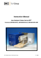
Instruction Manual Gas Sample Probes Series SP® Versions SP2000H/DIL, SP2000H/DIL/B, SP2000H/DIL/BR Gas sampling and gas conditioning technology 2-1.1.
Dear customer, we have made up this operating manual in such a way that all necessary information about the product can be found and understood quickly and easily. Should you still have any question, please do not hesitate to contact M&C directly or go through your appointed dealer. Respective contact addresses are to be found in the annexe to this operating manual. Please also contact our homepage www.mc-techgroup.com for further information about our products.
Content 1 2 3 4 5 6 7 General information ...................................................................................................................... 5 Declaration of conformity ............................................................................................................ 5 Safety instructions ........................................................................................................................ 6 Warranty ........................................................
List of illustrations Figure 1 Figure 2 Figure 3 Figure 4 Figure 5 Figure 6 Figure 7 Figure 8 Figure 9 Figure 10 Figure 11 Figure 12 Figure 13 Figure 14 Figure 15 Figure 16 Figure 17 Figure 18 Figure 19 Probe type SP2000H/DIL/2x wit second sample outlet (undiluted) ................................... 8 Probe type SP2000H/DIL/VA/B ......................................................................................... 9 Probe type SP2000H/DIL/BR ..........................................................
Head Office M&C TechGroup Germany GmbH Rehhecke 79 40885 Ratingen Germany Telephone: 02102 / 935 - 0 Fax: 02102 / 935 - 111 E - mail: info@mc-techgroup.com www.mc-techgroup.com 1 GENERAL INFORMATION The product described in this operating manual has been examined before delivery and left our works in perfect condition related to safety regulations. In order to keep this condition and to guarantee a safe operation, it is important to heed the notes and prescriptions made in this operating manual.
3 SAFETY INSTRUCTIONS Please take care of the following basic safety procedures when mounting, starting up or operating this equipment: Read this operating manual before starting up and use of the equipment. The information and warnings given in this operating manual must be heeded. Any work on electrical equipment is only to be carried out by trained specialists as per the regulations currently in force.
5 USED TERMS AND SIGNAL INDICATIONS DANGER! This means that death, severe physical injuries and/or important material damages will occur in case the respective safety measures are not fulfilled. WARNING! This means that death, severe physical injuries and/or important material damages may occur in case the respective safety measures are not fulfilled. This means that minor physical injuries may occur in case the respective safety measures are not fulfilled.
6 INTRODUCTION Dilution probes are used wherever dilution of the sample gas is necessary for the measurement of one or several sample gas components. Examples are the measurement of toxic gas components, moisture measurements or adjustment of the sample gas concentration to the analyser measuring range. M&C dilution probes type SP2000H/DIL... are based on the modular probe type SP2000-H.
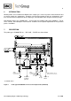
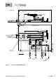
View "A" Bypass out Bypass-T Bypass gas A A Pre-heater Filter Check valve Filter Crit. orifice Ball valve Option VA Cal gas Pressure gauge -1...0bar Dil gas Sample out diluted Bypass gas Figure 2 Probe type SP2000H/DIL/VA/B Gas sampling and gas conditioning technology 2-1.1.
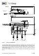
View "A" Bypass gas Bypass back to The process A A Filter Filter Pre-heater Crit. orifice Check valve Cal gas Figure 3 Pressure gauge -1…0bar Dil gas Sample out diluted Probe type SP2000H/DIL/BR To prevent cooling below dew point at the dilution point, the dilution unit with critical orifice is installed temperature-stable in the heated part of the gas sample probe directly in the clean gas outlet. A gas pre-heater heats the dilution gas to probe temperature. With the option ..B/..
The probe can also be provided with an optional hand-operated, heated shut-off ball valve in the inlet VA (see Fig. 2) for the purpose of sealing off the filter space from the sampling process during filter replacement. Another option is the second sample outlet for undiluted gas (..2x, see Fig.1) A precision pressure regulator with pressure gauge serves for adjustment of the necessary dilution gas supply pressure. The function of the dilution injector is monitored via a vacuum pressure gauge.
7.1 VARIATIONS The gas flow patterns of the available probe variants are shown in the following figure.
8 TECHNICAL DATA Technical data SP series ® Weather protective cover Electrical connection Degree of protection of terminal box Mains supply Material of medium contacted parts Ambient temperature Dilution probe version SP2000H/DIL .. Yes Terminals; max. 4 mm² IP54 EN60529 230V 50/60Hz, 800W or 115V 60Hz, 800W (fuse 10A) Stainless steel 1.4571, 1.
9 DILUTION PRINCIPLE The functional principle of the dilution probe is based on ultrasonic flow through a critical orifice (see Fig. 4). The flow through the orifice is constant when the differential pressure via the orifice is higher than 500mbar. For the atmospheric inlet pressure (Poin = 1020mbar), this means a pressure at the orifice outlet (Pout) of less than 520mbar absolute. The necessary vacuum at the orifice outlet is produced by an injector operated with dilution gas.
10 DIMENSIONS The dimensions of the SP2000H/DIL/2x probes are shown below. 340 345 260 1) 1/4"NPT Dil gas in Power Low temperature 230V,50Hz alarm contact (115V,60Hz)(a) Tube 6x1mm o Tube 8x1mm o Sample out Dil gas Tube 6x1mm o Tube 6x1mm o Cal gas Sample out undiluted Pressure gauge -1…0bar Dil gas Tube 8x1mm * (Inj. I) Sample diluted 2) 1) Implementation of the cal gas valve only with 180°C version; With 320°C version assembling in the angular sheet.
Place the sampling point so that sufficient space is available for installation and removal of the probe, taking into account the insertion length of the sample pipe. Ensure good access to the probe for ease of maintenance. Dimension the local sample connection so that the temperature of the connection is always above the acid dew point to prevent corrosion and blockage problems. If this is not possible, a heated sample pipe type SP35/SP30 is recommended for a cold orifice.
NOTE! When using the heated sample pipe or pre-filter V12 in conjunction with probes with the bypass return option ..BR, a short-circuit between the bypass gas and sample inlet in the centre of the probe flange must be prevented or low sample gas readings will be obtained. Make sure that the gasket for the mounting flange does not block the bypass return connection or the probe will not function properly.
Option –A/A1 When ordering option –A or -A1, the sets, consisting of pressure regulators and pressure gauges, are mounted directly on the probe (see Fig.2). Connection of the sample pipe takes place at the elbow union of the probe (see above). Option –S/S1 For option –S or - S1, the necessary pressure regulators, pressure gauge, shut-off valves and flow meter are installed externally in a 19“ control panel (see Fig. 4).
13.4 CONNECTION OF CALIBRATING GAS The dilution heated probe is provided with a check valve as standard, opening at pressures above 0.7bar. In both versions, a pipe union DN4/6mm (1/4“ o for 115V version) is available for connection of the calibrating gas. 13.5 ELECTRICAL CONNECTION Temperature setting of the SP2000H/DIL... probes takes place with a capillary regulator as standard. The probe can also be provided with an optional PT100 or thermocouple.
13.5.1 TYPES WITH INTERNAL CAPILLARY TUBE HERMOSTAT Remove cover of connection box. The electrical wiring diagram is located in the cover. Insert mains cable (min. 3x1.5mm2) through cable gland and connect to appropriate terminals. Insert signal cable (under-temperature alarm) through cable gland and connect to appropriate terminals (the contact Tu shows the alarm event). Screw cover back in place.
14 INITIAL USE Prior to initial use, system and process-specific safety measures must be observed. For the media to be transported, the relevant safety requirements and measures must be taken into account. WARNING! The air supply to the injectors should not be turned on until the probe is at operating temperature (see. technical data). Or damage to the probe or/and inconsistent initial dilution ratio can result.
An extract from an injector data sheet is shown below. Injektor-Datenblatt / Injector data sheet Injektortyp Injektor-Nr. I 689 Injector type Injector No. Betriebsdruck Operating pressure [bar] 2,4 2,6 2,8 3,0 3,2 3,4 3,6 3,8 4,0 Für Sonden-Nr. 8652/222835 For probe No.
In the event of under-temperature (failure of probe heating), the dilution gas supply must be interrupted! WARNING! 14.1 CALIBRATION Calibration of the downstream analyser system or checking the dilution factor must always take place under process conditions. An appropriate calibration gas can be supplied via the cal gas valve. NOTE! The gas pressure must be higher than 0.7 bar, as the vacuum valve mounted on the probe has an opening pressure of 0. 7 bar.
16 MAINTENANCE Prior to maintenance and repairs, system and process-specific safety measures must be observed. Aggressive condensation possible. Safety goggles and appropriate protective clothing should be worn! WARNING! Caution: Do not touch the probe surface during use as this can cause burns due to the high surface temperatures.
16.1 REPLACEMENT OF FILTER ELEMENT AND SEALS WARNING! Before carrying out any maintenance or repairs, it must be ensured that no health-endangering contaminants remain in the probe. A suitable measure is, e.g. purging the probe with inert gas. The bypass respectively primary injector air supply should be turned off before the probe filter lid assembly is removed.
The following pictures should explain the above mentioned steps. Figure 12 Removing the new filter housing lid Unscrew filter knurled screw, inspect filter element and replace if necessary. Inspect filter element seals and replace if necessary. Inspect O-rings (for /320H.. flat graphite gasket, for /7aT PTFE sealing rings) in cover and replace if necessary. Clean filter space. NOTE! It is now also possible to clean the sample pipe to remove deposits. Caution ceramic probe tubes.
16.2 DISMANTLING THE DILUTION CROSS Figure 11 shows an exploded drawing of the dilution unit. 180°C Version Nut 1 Nut 2 Critical orifice Injector O-rings Block Nut 4 Nut 3 Mark Mark Nut 6 Figure 13 Nut 5 Mark Tube sample gas out Exploded drawing of dilution unit The following step-by-step procedure is recommended: Remove probe insulating cover (see 16.1). Loosen knurled screw for fixing heat conducting plates. Remove heat conducting plates.
16.2.1 CHANGE AND CLEANING OF THE CRITICAL ORIFICE (180°C VERSION) Do not clean the critical orifice mechanically. Cleaning should take place in an ultrasonic bath! WARNING! Figure 14 shows the position of the orifice in the crosspiece and the o-ring seals (180°C version). Sucking pipe Mounting tool Part No.: 93S4040 Orifice 2 1 3 Jet pipe Injector Nut 3 Pos. 2: Sealing set for critical orifice consisting of 2 o-rings Part No.
16.2.2 CHANGING THE PACKING AT THE CRITICAL ORIFICE ( 320°C-VERSION) When the orifice is removed please change the packing (320°C- version) as well. Figure 15 shows the dilution cross with the orifice and the packing (320°C version). Sucking pipe Mounting tool Part No.: 93S4040 Orifice 2 1 3 Jet pipe Injector Nut 3 Pos. 2: Packing for critical orifice consisting of 4 graphite seals 3,2/ 6 – 1,5mm thickness plus plain washer 3,3/ 6 Part No.
16.2.3 CHANGE AND CLEANING OF THE INJECTOR NOTE! WARNING! 16.2.4 For cleaning the injector it is not necessary to remove it out of the dilution cross. Clean the nozzle mechanically. For the 180°Cversion the complete cross can be cleaned up in an ultrasonic bath. The complete cross of the 320°C-version can not be cleaned in an ultrasonic bath. Otherwise the graphite packing will be damaged ! Before cleaning the nozzle with compressed air remove the critical orifice first (s. 16.
Please change the packing as follows: Loosen union nut 3 and remove the jet pipe; Loosen nut 4 and remove the dilution tube connection; Push out the injector with the tool (Pos. 3) from the opposite side (jet pipe); Remove the thrust collar from the nozzle; Remove the graphite rings; Push on the nozzle and the 3 new graphite rings; Replace the thrust collar; Re-install the injector with the tool. Push it up to block and press it tightly. WARNING! 16.
16.3.1 CHANGE AND CLEANING OF THE BYPASS INJECTOR (180°C VERSION) NOTE! For cleaning the injector of the 180°C-vesion it is not necessary to remove it out of the Bypass-T. Clean the nozzle mechanically or put the complete cross into an ultrasonic bath. For the 320°C-version do not clean the complete cross in an ultrasonic bath because the graphite packing could be destroyed. A cleaning with compressed air has to be carried out from the sample outlet side (jet pipe).
The Swagelok® fittings must be carefully tightened to avoid damaging the internal components! WARNING! 16.3.3 CHANGE OF THE GRAPHITE PACKING AT THE BYPASS INJECTOR (320°C VERSION) When changing the injector the packing (320°C version) must be changed as well. Figure 16 shows the bypass injector unit of a 320°C version. Bypass-T Mounting tool Jet pipe Part No.: 93 S 4040 Injector complete, DIL-H320-BR Part No.: 93S4003 Pos.
17 SPARE PARTS Wear, tear and replacement part requirements depend on specific operating conditions. The following table gives an extract of recommended spares for the dilution probes type SP2000H/DIL... .
18 APPENDIX More product documentation is available on our Internet catalogue: www.mc-techgroup.com. Gas sampling and gas conditioning technology 2-1.1.