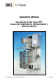
Operating Manual Gas Sample Probe Series SP® Version SP 2000-H320/S, SP2000-H320/S1, SP2000-H320/S2 Gas sampling and gas conditioning technology 2-1.1.
Dear customer, we have made up this operating manual in such a way that all necessary information about the product can be found and understood quickly and easily. Should you still have any question, please do not hesitate to contact M&C directly or go through your appointed dealer. Respective contact addresses are to be found in the annexe to this operating manual. Please also contact our homepage www.mc-techgroup.com for further information about our products.
Contents 1 2 3 4 5 6 General information ............................................................................................................... 5 Declaration of conformity ..................................................................................................... 5 Safety instructions................................................................................................................. 6 Warranty ...............................................................................
List of Illustrations Figure 1 Figure 2 Figure 3 Figure 4 Figure 5 Figure 6 Figure 7 Figure 8 Figure 9 Figure 10 Figure 11 Figure 12 Figure 13 Figure 14 Figure 15 Figure 16 Figure 17 Figure 18 Figure 19 Figure 20 Figure 21 Figure 22 Figure 23 Figure 24 Probe construction eg. version SP2000-H320/S1 .............................................................11 Mounting possibilities .........................................................................................................
HEAD OFFICE M&C TechGroup Germany GmbH Rehhecke 79 40885 Ratingen Germany Telephone: 02102 / 935 – 0 Fax: 02102 / 935 – 111 E - mail: info@mc-techgroup.com www.mc-techgroup.com 1 GENERAL INFORMATION The product described in this operating manual has been examined before delivery and left our works in perfect condition related to safety regulations. In order to keep this condition and to guarantee a safe operation, it is important to heed the notes and prescriptions made in this operating manual.
3 SAFETY INSTRUCTIONS Please take care of the following basic safety procedures when mounting, starting up or operating this equipment: Read this operating manual before starting up and use of the equipment. The information and warnings given in this operating manual must be heeded. Any work on electrical equipment is only to be carried out by trained specialists as per the regulations currently in force.
5 USED TERMS AND SIGNAL INDICATIONS DANGER! This means that death, severe physical injuries and/or important material damages will occur in case the respective safety measures are not fulfilled. WARNING! This means that death, severe physical injuries and/or important material damages may occur in case the respective safety measures are not fulfilled. This means that minor physical injuries may occur in case the respective safety measures are not fulfilled.
6 INTRODUCTION A great problem during extractive and continuous gas analysis are the escort substances of the gas such as dust, water vapour and also gas components that build up corrosive acids in connection with condensed water vapour. It may also occur that solid particles are precipitated when the gas is cooled down. Consequently, the downstream conditioning device would be choked.
7 APPLICATION The probes type SP2000-H320/S.. are used for continuous gas sampling in processes with high dust load and high temperatures and/or high gas humidity where additionally solid particles may precipitate. M&C has developed these probes for eg. continuous gas sampling in waste gas of DENOX plants (SCR) where NH3 is added to the flue gas in order to reduce the NOX content. With temperatures of <300 °C, ammonium salts are produced due to the chemical reaction of NH3 and SO2/SO3 in the flue gas.
9 DESCRIPTION The probes have been designed for easy mounting, safe operation, easy maintenance and a great variety of applications. The main features of this probe are: changing the filter element without tools and without necessity of dismounting the sample line, easy cleaning of the filter housing, cleaning of the sample tube without dismounting the probe. The big surface filter element is placed inside a heated filter receiving part of stainless steel.
1 2 3 5 4 6 Figure 1 10 Probe construction eg. version SP2000-H320/S1 RECEIPT OF GOODS AND STORAGE The gas sample probe and any special accessories should be removed carefully from the packaging and checked immediately for completeness against the delivery note; Check the goods for any damage incurred during transport and if necessary inform your transport insurer of any damage. The gas sample probe is normally delivered in two packaging units: 1.
Locate the sampling point in such a way that there is adequate space for inserting and removing the probe and pay attention to the insertion length of the probe tube! ! Make certain that the probe is easily accessible so that you can carry out any subsequent maintenance work without trouble.
12.1 DISMOUNTING THE FILTER HOUSING COVER AND CHECKING THE FILTERELEMENT For this purpose, the filter housing cover must be dismounted as follows: Figure 3 Schematic drawing of the filter housing cover Remove the protection cover; Turn the locking handle A for about one rotation to the left so that the lid is moved upwards; Put the handle C into position E; Swing the clamp clip B to the left (into direction G); Pull the filter housing lid out using the locking handle A.
The following photos show how to execute the above mentioned steps. Figure 4 Dismounting of the filter housing lid Check on the filter screw I whether the filter element J has been screwed hand-tight (see figure 20). Then put in again the filter receiving part, set the handle C into position E, swing the clamp clip back again and tighten the lid with the locking handle A.
12.2 TEMPERATURE REGULATOR On version SP2000–H320/S the temperature regulation is effected by the capillary thermostat mounted inside the connecting box. The range of regulation is from 50 to 320°C. On the versions SP2000-H320/S1 and SP2000-H320/S2 the regulation is made by means of an external electronic regulator. M&C supplies appropriate temperature regulators, eg. Type 703G (see data sheet 2-5.1) or Type 703G double that can be mounted separately or directly on the gas sample probe (max.
If there is a high dust load in the process gas, we urgently recommend the use of a pre-filter in order to increase the service life. They can be supplied with a volume displacement to shorten the response time. The pre-filters can be directly screwed into the probe flange or on request with extension tubes equipped with a volume displacer.
Sealing DN65 PN6 90S2077 17 Figure 6 Mounting the sample tube or pre-filter Gas sampling and gas conditioning technology 2-1.1.
13 SUPPLY CONNECTIONS 13.1 MOUNTING THE SAMPLE LINE Open the fastening clip of the sample line. Unscrew the union nut of the connecting adapter GL18-DN4/6 and put it together with the clamping ring in the correct order and direction over the 6mm PTFE core of the heated line. Put the PTFE core on the connection piece inside the connection adapter and fasten the union nut with clamping ring hand-tight. Shut the fastening clip of the sample line.
Calibration gas connection 6mm tube 1 2 Figure 8 13.3 Connection of test gas line and condensate evacuation CONNECTING THE CONDENSATE EVACUATION On versions SP2000-H320/S and SP2000-H320/S1 the condensate is evacuated via a peristaltic pump SR25.1. In order to carry away the condensate, a tube with 6mm outside diameter has to be connected to the condensate outlet DN4/6 . On version SP2000-H320/S2 no peristaltic pump is integrated because no condensate is arising. Aggressive condensate possible.
13.4 ELECTRICAL CONNECTION WARNING! WARNING! 13.4.1 Wrong supply voltage can destroy the equipment. when connecting the device, please ensure that the supply voltage is identical with the information provided on the type plate! Attention must be paid to the requirements of IEC 364 (DIN VDE 0100) when setting high-power electrical units with nominal voltages of up to 1000V, together with the associated standards and stipulations! A main switch must be provided externally.
13.4.2 VERSION SP2000-H320/S1 WITH ELECTRONIC TEMPERATURE CONTROLLER The gas sample probe is supplied either as unit with a fixed and electrically connected temperature controller, or the temperature controller is attached as separate unit for external mounting. Then, the electrical connection is to be made as follows: Remove the lid of the connection box on the gas sample probe. Inside the lid, you will find the terminal connection plan. Insert the mains cable (min.
The electrical connection of the temperature controller Type 703G is to be made according to the terminal connecting plan as shown in figure 10 and described as follows: Unscrew the housing lid. Insert the mains cable (min. 3 x 1,5 mm2, terminal range 6 – 12mm) into the left cable gland of the controller and connect it to the appropriate terminals. Insert the cable for the alarm contact (terminal range 6 – 12mm) into the right cable gland and connect it to the appropriate terminals.
Figure 11 Electrical connection SP2000-H320/S2 with electronic double controller 703G NOTE! As sensor line an equalization line has to be provided. The appropriate thermo equalization terminals are available inside the connection box. The electrical connection of the temperature controller Type 703G is to be made according the terminal connection plan as shown in figure 11 and being described as follows: Screw off the housing lid. Insert the mains cable (min.
CAUTION! 14 In case you should not have used all cable glands when connecting the temperature controller, it is important to shut the cable glands in order to provide the tightness of the housing. STARTING UP Before starting up, check whether the supply voltage corresponds to the indication on the type plate. Control whether the eventually integrated ball valve is connected. The turning handle of the hand operated ball valve must be in position on the right limit stop.
14.1 ADJUSTMENT OF THE SET VALUE TEMPERATURE If the sample probes are delivered together with the temperature controllers 703 or double 703, then the temperature controllers are parameterized for the sample probe. The adjusted set value of the temperature is 320°C for the sample probe and 180°C for the heated separator. In case there must be changed another parameter than the set value temperature, you can read how to proceed in the separate operating manual of the temperature controller 703 (2-5.1.
14.1.3 VERSION SP2000-H320/S2 The following steps have to be effected on the controller 703: Adjustment of the set value on the sample probe: Push the PGM-key for a short time. You can read “SP1” on the below display. Adjust the desired set value by using the arrow keys in the above display. Wait until the set value is flashing for a short time, then it is fixed. Push the PGM-key twice to return to the normal reading.
Figure 13 Schema of test gas (calibration gas) feeding via return valve 14.2.2 OPTION 3/2-WAY BALL VALVE /3VA320 When feeding the test gas, the probe is automatically separated from the process and, therefore, only a small quantity of test gas is necessary as no mixing with the sample gas may occur. 15 For the measurement operation, set the ball valve into the central position. For the test gas feeding, turn the ball valve to the right until the limit stop.
WARNING! Aggressive condensate possible. Wear protective glasses and protective clothes! WARNING! For works during operation: High surface temperatures! Any contact may lead to burnings. Wear protective gloves and protect the probe against unauthorized access! 16.1 REPLACEMENT OF THE STANDARD FILTER ELEMENT AND CONTROL OF THE SEALS Shut the ball valve (if present). Purge the probe if toxic gases have been used! Remove the protective cover.
Gas sample probe SP2000-H320/0,1GF with 0,1µ fibre glass filter element Mounting notice Screw in knurled screw “1” until the filter element is tightend slightly. Afterwards screw in the knurled screw “1” an additional rotation (360°) 1 2 3 4 5 6 7 Figure 14 Filter screw Gasket (30) Filter element 0,1 µm Adaptor ring stainl. Steel Gasket (69) Fixing disk Filter housing lid Mounting notice for probes with fibre glass filter element F-0,1GF 150 NOTE! 16.
Heating cartridge Thermostat Figure 15 Positioning of the thermostat and heating cartridge Remove the lid of the electrical connection box after having loosened the 4 screws. Unscrew both screws “A“ on the bottom of the connection box (figure 16) which are serving to mount the connection box on to the holding clip. Unscrew the hexagon head cap screws “B“ (figure 16) which are serving to fix the heating cartridge receiving plate and the thermostat sensor receiving plate.
Figure 17 Connection box with heating cartridge and thermostat sensor Disconnect on the terminal strip the electrical connection lines of the heating cartridge and of the thermostat. Tear off the turning knob on the thermostat. Remove both fixing screws being under there (see figure 18). Remove also the 2 fixing screws of the thermostat receiving plate. Tear out the heating cartridge through the cable gland “C“.
17 SPARE PARTS LIST Gas sample probe SP2000... (V) Consumable parts and (E) recommended spare parts Recommended quantity being in operation for [years] Part No. Description V/E 1 2 3 90 S 0020 Filter element Type S-2K150. Length 150mm, Material ceramic, Filter porosity: 2µm V 5 10 15 90 F 0125 Filter element Type F-0,1GF150. Length 150mm, Material glass fibre, Filter porosity: 0,1µm V 5 10 15 93 S 2096 Filter glass wool for probe SP2..00..
18 CONNECTION AND MOUNTING DATA Gas sample probe Type SP2000-H320/S Dimensions B x H x T 340 x 650 x 345 Material filter housing Stainl. Steel 1.4571* Sealing material Graphite Material probe flange seal Novapress Capacity: 250V,3A~, 0,25A=, Switching point: T 30 °C DN4/6 Low temperature alarm contact Connection gas outlet SP2000-H320/S1 See 703 Electrical connection Pipe Ø 6 mm 230V 50/60Hz, 800W, /115V** = 115V 60Hz, 800W Fuse 10A 2 Terminals max.
Figure 19 SP2000-H/Filter elements Gas sampling and gas conditioning technology 2-1.1.
Figure 20 High temperature sample tube max. 1800°C Gas sampling and gas conditioning technology 2-1.1.
Figure 21 Electrically heated sample tube SP30-H1.1/-H2 Gas sampling and gas conditioning technology 2-1.1.
Figure 22 SP2000-H320/S Gas sampling and gas conditioning technology 2-1.1.
Figure 23 SP2000-H320/S1 Gas sampling and gas conditioning technology 2-1.1.
Figure 24 SP2000-H320/S2 Gas sampling and gas conditioning technology 2-1.1.