OPERATING INSTRUCTIONS Gas Sample Probe SP® SP180-H Gas sampling and gas conditioning technology 2.
Dear customer, we have made up this operating manual in such a way that all necessary information about the product can be found and understood quickly and easily. Should you still have any question, please do not hesitate to contact M&C directly or go through your appointed dealer. Respective contact addresses are to be found in the annexe to this operating manual. Please also contact our homepage www.mc-techgroup.com for further information about our products.
Content 1 2 3 4 5 6 General information....................................................................................................................... 4 Declaration of conformity ............................................................................................................. 4 Safety instructions ........................................................................................................................ 5 Warranty ............................................................
Head Office M&C TechGroup Germany GmbH Rehhecke 79 40885 Ratingen Germany Telephone: 02102 / 935 - 0 Fax: 02102 / 935 - 111 E - mail: info@mc-techgroup.com www.mc-techgroup.com 1 GENERAL INFORMATION The product described in this operating manual has been examined before delivery and left our works in perfect condition related to safety regulations. In order to keep this condition and to guarantee a safe operation, it is important to heed the notes and prescriptions made in this operating manual.
3 SAFETY INSTRUCTIONS Please take care of the following basic safety procedures when mounting, starting up or operating this equipment: Read this operating manual before starting up and use of the equipment. The information and warnings given in this operating manual must be heeded. Any work on electrical equipment is only to be carried out by trained specialists as per the regulations currently in force.
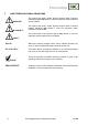
5 USED TERMS AND SIGNAL INDICATIONS DANGER! This means that death, severe physical injuries and/or important material damages will occur in case the respective safety measures are not fulfilled. WARNING! This means that death, severe physical injuries and/or important material damages may occur in case the respective safety measures are not fulfilled. This means that minor physical injuries may occur in case the respective safety measures are not fulfilled.
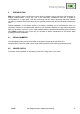
6 INTRODUCTION M&C gas sample probes provide direct insitu ultra-fine filtration during continuous gas sampling for analytic measurements. In this way, part of the necessary maintenance work for a system is concentrated on a single point. This filter technology has the major advantage that dust mixtures consisting of ultra-fine and coarse dusts can be optimally retained with the least possible maintenance work.
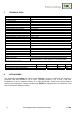
7 TECHNICAL DATA Gas Sample Probe Series SP® Part No.
DESCRIPTION The sample probes are designed for easy installation, reliable operation and trouble-free maintenance.
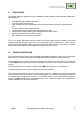
The following cross-sectional drawing shows the probe SP180-H. Figure 1 11 Dimensions and construction of the SP180-H RECEPTION The gas sample probe normally is delivered in two packaging units: 1. The gas sample probe with the required screws, nuts and flange sealing. 2. Sample tube with gasket. The gas sample probe should be removed carefully from the packaging and checked immediately for completeness against the delivery note.
12 PREPARATION FOR INSTALLATION Select the optimal sampling point in accordance with the generally applicable guidelines or consult the competent persons. Locate the sampling point in such a way that there is adequate space for inserting and removing the probe and pay attention to the insertion length of the probe tube. Make certain that the probe is easily accessible so that you can carry out any subsequent maintenance work without trouble.
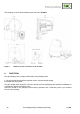
After mounting of the probe at the sampling flange put the heat insulating protection cover over the probe flange again and secure it with the metal clamp . NOTE! Figure 2 13.1 A preferred mounting position is to have the probe with its sample gas outlet pointing downwards, although this is not absolutely necessary for perfect functioning.
.2 14 CONNECTION OF THE TEST GAS LINE For connection of the test gas line a threaded tube connector for dimension Ø 6x1mm (DN4/6) is available (see Figure 1) If a PTFE tube is used as sample line, a carrying bracket must under all circumstances be inserted in the end of the tube in order to prevent the tube being pressed together. The temperature-resistant, stainless steel connectors supplied by M&C has a double-blade ring system to ensure reliable sealing.
Figure 3 15 Electrical connection diagram STARTING UP Before starting up check whether the mains power supply voltage corresponds with the information stated on the probe's nameplate. Switch on mains power supply. The total heating-up time is approximately 2 hours. After about 1 hour the probe is already sufficiently heated for the temperature to have exceeded the temperature failure alarm value (160°C), but it still takes about another hour until operating temperature is reached.
An indication that probe-maintenance may be necessary could be shown by a constant decline in the amount of sample gas in the analysis system. Probe maintenance is restricted essentially to replacing filter elements and checking seals: WARNING! Aggressive condensate is possible. Wear protective glasses and proper protective clothing! High surface temperatures! Wear protective gloves! Remove insulation cap by pressing it together (see Figure 4); CARE! Figure 4 2.
Loosen probe lid by turning handle left and pull it out with o-rings , filter element sealings , filter element with filter element holder and filter’s knurled screw ; Screw out the filter’s knurled screw and renew filter element ; Check filter element seals and replace if necessary; Check lid o-rings and change if necessary; Clean filter chamber; It is also possible to rod through the probe tube in order to remove deposits. Remounting happens in reverse order.
18 SPARE PARTS LIST Wear, tear and replacement part requirements depend on specific operating conditions. The recommended quantities are based on experience and they are not binding. Gas sample probe SP180-H (C) Consumable parts (R) Recommended spare parts (S) Spare parts Part No. 90 S 0015 93 S 0045 93 S 0020 93 S 0025 90 S 2080 90 S 2077 90 S 2075 93 S 2105 93 S 2110 19 Indication Ceramic filter element S-2K, 2 µm, 75 mm Viton - gasket (30) O-ring lid sealing (39) Material: Viton.