Operating instructions Gas sample probe Serie SP® Version SP10, SP10-H Gas sampling and gas conditioning technology 2-0.1.
Dear customer, we have made up this operating manual in such a way that all necessary information about the product can be found and understood quickly and easily. Should you still have any question, please do not hesitate to contact M&C directly or go through your appointed dealer. Respective contact addresses are to be found in the annexe to this operating manual. Please also contact our homepage www.mc-techgroup.com for further information about our products.
Content 1 2 3 4 5 6 7 8 9 10 11 12 13 14 15 16 17 18 19 General information ..................................................................................................................... 4 Declaration of conformity ........................................................................................................... 4 Safety instructions....................................................................................................................... 5 Warranty ..........................
Head Office M&C TechGroup Germany GmbH Rehhecke 79 40885 Ratingen Germany Telephone: 02102 / 935 - 0 Fax: 02102 / 935 - 111 E - mail: info@mc-techgroup.com www.mc-techgroup.com 1 GENERAL INFORMATION The product described in this operating manual has been examined before delivery and left our works in perfect condition related to safety regulations.
3 SAFETY INSTRUCTIONS Please take care of the following basic safety procedures when mounting, starting up or operating this equipment: Read this operating manual before starting up and use of the equipment. The information and warnings given in this operating manual must be heeded. Any work on electrical equipment is only to be carried out by trained specialists as per the regulations currently in force.
5 USED TERMS AND SIGNAL INDICATIONS DANGER! This means that death, severe physical injuries and/or important material damages will occur in case the respective safety measures are not fulfilled. WARNING! This means that death, severe physical injuries and/or important material damages may occur in case the respective safety measures are not fulfilled. This means that minor physical injuries may occur in case the respective safety measures are not fulfilled.
6 INTRODUCTION M&C gas sample probes provide direct insitu ultra-fine filtration during continuous gas sampling for analytic measurements. In this way, part of the necessary maintenance work for a system is concentrated on a single point. This filter technology has the major advantage that dust mixtures consisting of ultra-fine and coarse dusts can be optimally retained with the least possible maintenance work.
The M&C gas sample probes SP10 respectively SP10-H are used for continuous gas sampling in processes with dust loadings up to 10g/m3, operating pressures up to max. 6 bar abs., temperatures up to max. 600C and high gas humidities. The modular design allows the combination of different pre-filter materials (max. 900°C) and length (>10g/m3) and therefore an optimum adaption to the process conditions. The compact design requires only little space.
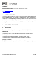
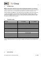
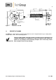
**V10-1, V10-2 **600 250 **555 *V10, V10-0 *270 14 90 *225 M&C 60 46 SP 10-H Power In 250 130 Terminal box with thermostat Heating element Optional with Volume displacer 1" 1/8"NPT Sample out Heat conductivity shells for tube fitting Figure 1 11 Dimensions SP10-H RECEIPT OF GOODS The M&C gas sample probe is normally delivered in one unit. It comprehends the gas sample probe with pre-filter, screws, nuts and flange gasket.
12 PREPARATION FOR INSTALLATION Please pay attention to the following points: Select the optimal sampling point in accordance with the generally applicable guidelines or consult the competent persons. Locate the sampling point in such a way that there is adequate space for inserting and removing the gas sample probe and pay attention to the insertion length of the probe tube.
NOTE! If a PTFE tube is used as sample line, an insert must be installed in the end of the tube in order to prevent the tube being pressed together ! Now place the heat conductivity shells on the connection of the gas sample line and prove it’s fit to prevent cold spots. 14 ELECTRICAL CONNECTIONS For the electrical installation take the relevant safety instructions into consideration. Before connecting the probe ensure that the mains is voltage-free.
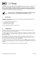
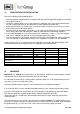
Carry out the following steps: Sensor Tset 315W(300W) 12 34 NL L Power 230V 50Hz (115V 60Hz) Figure 2 Electrical connection SP10-H Remove the lid of the junction box; Insert the mains cable (min. 3 x 1.5 mm2) through the cable gland and connect it to the appropriate terminals as in the wiring above; Screw lid back on; 15 START UP Before starting up check whether the mains power supply voltage corresponds with the information stated on the probe’s nameplate.
16 MAINTENANCE The safety instructions specific to the plant and process are to be consulted prior to any maintenance work! WARNING! Before starting maintenance work on electrical parts ensure that the mains and the eventually connected alarm and control circuits are switched off completely! Maintenance cycles have to be carried out depending on your process or ambient conditions.
18 SPARE PARTS LIST Wear, tear and replacement part requirements depend on specific operating conditions. The recommended quantities are based on experience and they are not binding. M&C Gas sample probe SP®10, SP®10-H (C) Consumable part (R) Recommended spare parts (S) Spare parts Part No.