Instruction Manual Gas Conditioning and Sampling System PSS® type PSS-5 and PSS-5/3 Gas sampling and gas conditioning technology 4-2.1.
Dear customer, we have made up this operating manual in such a way that all necessary information about the product can be found and understood quickly and easily. Should you still have any question, please do not hesitate to contact M&C directly or go through your appointed dealer. Respective contact addresses are to be found in the annexe to this operating manual. Please also contact our homepage www.mc-techgroup.com for further information about our products.
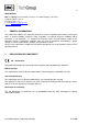
List of Contents 1 General information ................................................................................................................. 4 2 Declaration of conformity ....................................................................................................... 4 3 Safety instructions ................................................................................................................... 5 4 Warranty .....................................................................
HEAD OFFICE M&C TechGroup Germany GmbH Rehhecke 79 40885 Ratingen Germany Telephone: 02102 / 935 – 0 Fax: 02102 / 935 – 111 E - mail: info@mc-techgroup.com www.mc-techgroup.com 1 GENERAL INFORMATION The product described in this operating manual has been examined before delivery and left our works in perfect condition related to safety regulations. In order to keep this condition and to guarantee a safe operation, it is important to heed the notes and prescriptions made in this operating manual.
3 SAFETY INSTRUCTIONS Please take care of the following basic safety procedures when mounting, starting up or operating this equipment: Read this operating manual before starting up and use of the equipment. The information and warnings given in this operating manual must be heeded. Any work on electrical equipment is only to be carried out by trained specialists as per the regulations currently in force.
5 USED TERMS AND SIGNAL INDICATIONS DANGER! This means that death, severe physical injuries and/or important material damages will occur in case the respective safety measures are not fulfilled. WARNING! This means that death, severe physical injuries and/or important material damages may occur in case the respective safety measures are not fulfilled. This means that minor physical injuries may occur in case the respective safety measures are not fulfilled.
6 INTRODUCTION The portable gas conditioning and sampling system PSS-5... has been especially designed so that precise gas analyses can be carried out in any place and at any time. The entire gas conditioning system is housed in a compact and robust aluminium case which ensures that the components can be removed easily, and gas analyses carried out quickly, safely and with a minimum amount of maintenance.
8 TECHNICAL DATA Gas Conditioning Type Sample outlet dew point PSS-5 PSS-5/3 range of adjustment: +2 °C … +15 °C, factory setting: +5 °C Dew point stability at const. conditions: < ±0,1°C Sample inlet temperature **max. 80°C* optional: **max. 180°C with stainless steel bulkhead union Sample inlet dew point **max. +80°C Gas flow rate **max. 150Nl/h **max. 350Nl/h Ambient temperature **+5°C up to +40°C Storage temperature -25°C up to +65°C Pressure 0,7bar up to 1,4bar abs.
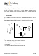
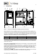
9 DESCRIPTION 11 EIN AUS Kondensat Meßgas max. 1800VA AUS GL18 440 >°C ON <°C Cooler ECP GL25 255 Figure 2 540 Design of the conditioning and sampling system PSS-5 and PSS-5/3 All the components of the gas conditioning system can be easily removed from the portable case 1 . The door of the case 2 can be opened by moving the toggle-type fasteners 3 on the side and the top to the left.
The 4/6 mm hose connections for the condensate and measuring leads 11 are located on the righthand side of the case (see figure 2 and 3). The stainless steel sample probe (0,5 m length, 6 mm diameter) and the 3 m sample line (DN 4/6 mm) are delivered with all models. The ventilation grids located in the lid and the left-hand side of the case ensure that the equipment is sufficiently ventilated. Options: The gas conditioning and sampling system PSS-5...
10 RECEIPT OF GOODS AND STORAGE The gas conditioning and sampling system PSS-5... is a completely pre-fitted unit. Please take the gas conditioning system and possible special accessories carefully out of the packaging material immediately after arrival, and compare the goods with the items listed on the delivery note; Check the goods for any damage caused during delivery and, if necessary, notify your transport insurance company without delay of any damage discovered.
12 SUPPLY CONNECTIONS 12.1 HOSE CONNECTIONS NOTE! Do not mix up the hose connections: they are clearly marked. After all the hoses have been connected, the tightness of such leads should be checked. Figure 3 shows the possible medium connections. These are located in the right-hand side of the gas conditioning case at the rear in a specially immersed assembly frame. Option: Electrical connection for heated sample line max.
Place the sealing ring over the connecting hose with the thicker bead towards the nut. Place the hose over the nipple on the thread. The tightness of the connections can only be guaranteed if the connecting hose has a straight rim (hose cutter). NOTE! The union nut is to be screwed tight by hand. The hose will no longer be able to slip off, and is now compression-proof. The hoses are to be removed in the reverse order. Aggressive condensate possible.
12.2 ELECTRICAL CONNECTIONS WARNING! NOTE! False supply voltage can demage the equipment.
Option temperature controller 701 for heated sample lines: For the electrical supply and control of a heated sample line with PT-100 a 7-pin plug at the side is available. The connection power is max. 6A, 1380W for the 230V version resp. 6A, 690W for the 115V-version. The maximum length of the heated sample line which can be used is calculated as follows: max. connection power [W] - power draw of heated components (i.e.
NOTE! The following minimal gas flow rates have been determined on the basis of the requirements of the maximum pressure on both sides of the gas measuring pumps N3-KPE and N9-KPE: N 3 KPE approximately 60NL/h air, N 9 KPE approximately 200NL/h air Premature damage can be caused to the pump membrane if less than the minimal total amount of flow is extracted as a result of excess pressure.
The frequency of the maintenance work depends on the operational process and can therefore only be determined in each individual case. Maintenance instructions pertaining to individual components can be found in the instruction manual for individual components. All parts which require maintenance work are housed in the gas conditioning system in such a way so that they are easily accessible. These are (see figure 2): The filter element of the preliminary filter FP-2T.
16 TROUBLE SHOOTING The following table aims to point out possible operational problems and offer solutions to such problems (not applicable during the starting procedure). Indication Problem Possible Cause Interruption of No voltage; gas flow; Upper LED on cooler does not come on; Middle LED on Cooler in cooler is green; operation but gas flow interrupted; Alarm LED on the LA electronics is red (see 4); Cooler does not function. Cooler alarm registers ‘excess temperature’.
Indication Problem Middle LED on Cooler and cooler is green; gas pump in operation; condensate in sample gas lead; LED of the LA electronics is green (see 4). Possible Cause Pre-filter clogged up; Check/Solution Peristaltic pump SR25.1 faulty; Remove filter from condensate lead; Pump delivering? Change filter; Pump not delivering? Change pump hose (see manual peristaltic pump SR25.1, 3-7.1-ME); OK? Check peristaltic pump (see manual peristaltic pump SR25.1, 3-7.
17 SPARE PARTS LIST Wear, tear and replacement part requirements depend on specific operating conditions. The recommended quantities are based on experience and are not binding. For spare parts of components which are not presented in the following list please see the specific instruction manuals or leaflets added in the appendix. Portable Sampling System Versions PSS-5, PSS-5/3 (C) consumable parts, (R) recommended spare parts, (S) spare parts recommended quantity PSS-5...
Portable Sampling System Versions PSS-5, PSS-5/3 (C) consumable parts, (R) recommended spare parts, (S) spare parts recommended quantity PSS-5...
18 APPENDIX Circuit diagram PSS-5 and PSS-5/3 More product documentation is available in our Internet catalogue: www.mc-techgroup.com Instruction manual electric gas cooler ECP 1000, ECP3000 Document : 3.1.1-ME Universal-Filters FP, FT, FPK, FS, FSS Document : 5-1.1 Instruction manual diaphragm pump Series N Document : 6-1.2.1-ME Instruction manual peristaltic pump SR25.1, SR25.1-G, Document : 3-7.1-ME Liquid alarm sensor LA1S and electronic controllers type LA1.4 Document : 5-5.1.
Figure 4 Circuit diagram PSS-5 and PSS-5/3, 115V and 230V Gas sampling and gas conditioning technology 4-2.1.