
Operator's manual Owner's manual

12
Gas sampling and gas conditioning technology 4-2.1.2-ME
12 SUPPLY CONNECTIONS
12.1 HOSE CONNECTIONS
NOTE!
Do not mix up the hose connections: they are clearly marked.
After all the hoses have been connected, the tightness of such
leads should be checked.
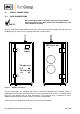
Figure 3 shows the possible medium connections. These are located in the right-hand side of the gas
conditioning case at the rear in a specially immersed assembly frame.
Power
supply
Sample gas
Out
Out
Condensate
In
Sample gas
Figure 3 Medium connections
All hose connections are equipped with 4/6mm sealing ring threaded hose couplings made of
polypropylene (PP) for gas input temperatures of up to a maximum of 80°C (see 3.). If heated sample
lines are used, whereby the gas input temperatures are increased up to a maximum of 180°C,
additional bulkhead unions made of stainless steel are recommended.
Connection hoses with dimensions DN 4/6mm are utilised for all models.