Instruction Manual Portable Gas Conditioning and Sampling System PSS® Types PSS-10/1 Gas sampling and gas conditioning technology 4-2.1.
Dear customer, we have made up this operating manual in such a way that all necessary information about the product can be found and understood quickly and easily. Should you still have any question, please do not hesitate to contact M&C directly or go through your appointed dealer. Respective contact addresses are to be found in the annexe to this operating manual. Please also contact our homepage www.mc-techgroup.com for further information about our products.
Content 1 General information ................................................................................................................ 4 2 Declaration of conformity....................................................................................................... 4 3 Safety instructions .................................................................................................................. 5 4 Warranty .................................................................................
HEAD OFFICE M&C TechGroup Germany GmbH Rehhecke 79 40885 Ratingen Germany Telephone: 02102 / 935 – 0 Fax: 02102 / 935 – 111 E - mail: info@mc-techgroup.com www.mc-techgroup.com 1 GENERAL INFORMATION The product described in this operating manual has been examined before delivery and left our works in perfect condition related to safety regulations. In order to keep this condition and to guarantee a safe operation, it is important to heed the notes and prescriptions made in this operating manual.
3 SAFETY INSTRUCTIONS Please take care of the following basic safety procedures when mounting, starting up or operating this equipment: Read this operating manual before starting up and use of the equipment. The information and warnings given in this operating manual must be heeded. Any work on electrical equipment is only to be carried out by trained specialists as per the regulations currently in force.
5 USED TERMS AND SIGNAL INDICATIONS DANGER! This means that death, severe physical injuries and/or important material damages will occur in case the respective safety measures are not fulfilled. WARNING! This means that death, severe physical injuries and/or important material damages may occur in case the respective safety measures are not fulfilled. This means that minor physical injuries may occur in case the respective safety measures are not fulfilled.
6 INTRODUCTION The portable gas conditioning and sampling system PSS-10/1 has been especially designed so that precise gas analyses can be carried out in any place and at any time. The entire gas conditioning system is housed in a compact and robust aluminium case which ensures that the components can be removed easily, and gas analyses carried out quickly, safely and with a minimum amount of maintenance.
8 TECHNICAL DATA Gas conditioning unit Sample outlet dew point Dew point stability Sample inlet temperature Sample inlet dew point Gas flow rate Ambient temperature Storage temperature Pressure Total cooling capacity at 25°C ambient temperature Number of gas inlets Number of gas outlets Medium connections Material of sample contacting parts Ready for operation Power supply Power consumption Fuse protection Electrical connection Case protection Housing Housing dimensions (H x W x D) Weight Part No.
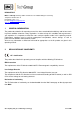
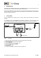
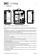
9 DESCRIPTION Sample IIn GL 18 Power 4 555 Sample Out 3 Condensate Out 5 8 GL 25 290 Figure 2 420 Design of the portable conditioning and sampling system PSS-10/1 All the components of the gas conditioning system can be easily removed from the portable case. The door of the case can be opened by moving the toggle-type fasteners on the side and the top to the left.
Options The gas conditioning and sampling system PSS-10/1 consists of standard one gas-measuring outlet terminal. An additional flow meter (DK800R), with needle valve, can be fitted to this terminal, whereby the adjustment of the terminals is carried out in accordance with the specified volume flow rate (see 3.).
10 RECEIPT OF GOODS AND STORAGE The portable gas conditioning and sampling system PSS-10/1 is a completely pre-fitted unit. The sample gas probe, sample gas line, connection cable and instruction manual are located in the inside part of the case door.
12 SUPPLY CONNECTIONS 12.1 HOSE CONNECTIONS NOTE! Do not mix up the hose connections: they are clearly marked. After all the hoses have been connected, the tightness of such leads should be checked. Figure 3 shows the possible medium connections. These are located in the right-hand side of the gas conditioning case at the rear in a specially immersed assembly frame.
The sample gas hoses, and condensation hoses, are to be assembled as follows: Remove the union nut from the sealing ring couplings by turning it anti-clockwise. The nut should be removed from the thread with great care so as to ensure that the loose sealing ring in the nut is not lost. Place the union nut over the connecting hose. Place the sealing ring over the connecting hose with the thicker bead towards the nut. Place the hose over the nipple on the thread.
The PSS-10/1 gas conditioning system is available with either 230V/50 Hz or with 115V/60Hz. A 6,3A fuse is used on all models as fuse protection. The fuse is located in the power socket of the PSS enclosure. In the event that a temperature controller is used in conjunction with heated sample lines, the overload protection level is increased to 10A. The electrical connection is carried out by means of a cold appliance plug and 2m of cable located on the left-hand side of the case.
13 STARTING Before starting the gas conditioning system please pay attention to the site-oriented and processoriented precautions.
14 CLOSING DOWN NOTE! The area in which the equipment is situated when not in use must be kept free of frost at all times. There are no special regulations to be observed if the gas conditioning and sampling system is to be close down for a short period of time. In the case of a long-term closing down, for example after a series of measurements has been completed, it is recommended that the gas conditioning system be washed with ambient air or inert gas.
15 MAINTENANCE Before the maintenance work is carried out, it is necessary that the specific safety procedures pertaining to the system and operational process be observed! WARNING! Dangerous voltage. It is necessary to take the equipment off the mains before any assembly, maintenance or repair work is carried out. The frequency of the maintenance work depends on the operational process and can therefore only be determined in each individual case.
16 TROUBLE SHOOTING The following table aims to point out possible operational problems and offer solutions to such problems (not applicable during the starting procedure). Indication Problem Possible Cause Interruption of No voltage; gas flow; Upper LED on cooler does not come on; Middle LED on Cooler in cooler is green; operation but gas flow interrupted; Alarm LED on the LA electronics is red Cooler does not function. Cooler alarm registers ‘excess temperature’.
Indication Problem Middle LED on Cooler and cooler is green; gas pump in operation; condensate in sample gas lead; LED of the LA electronics is green; Possible Cause Check/Solution Pre-filter clogged up; Remove filter from condensate lead; Pump delivering? Change filter; Pump hose faulty; Pump not delivering? Change pump hose (see manual SR25.1, Peristaltic pump 3-7.1-ME); OK? SR25.1 faulty; Check peristaltic pump (see manual SR25.1, Not sufficient drying of 3-7.
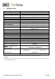
17 SPARE PARTS LIST Wear, tear and replacement part requirements depend on specific operating conditions. The recommended quantities are based on experience and are not binding. For spare parts of components which are not presented in the following list please see the specific instruction manuals or leaflets mentioned in the appendix.
Portable Sampling System Version PSS-10/1 (C) consumable parts, (R) recommended spare parts, (S) spare parts recommended quantity PSS-10/1 being in operation [years] C/R/S 1 2 3 Diverse: 90 G 0006 Pre-filter PF 2 for condensate pump SR25.1 C 5 10 15 90 K 6030 Fine fuse 4A T, 5mmx20mm for PSS... R 5 5 5 90 G 0020 Fine fuse 10A T, 5mmx20mm for PSS... R 5 5 5 with option temp.
Connecting the heated sample line with special adapter Sample gas IN Bulkhead union Back ferrule 6mm Øi Union nut 10mm Øi Heated sample line Adapter PSS...
Figure 4 Circuit diagram PSS-10/1, 115V and 230V Gas sampling and gas conditioning technology 4-2.1.