
Operator's manual Owner manual

20
Gas sampling and gas conditioning technology 9-3.15-ME
16.3 ELECTRICAL CONNECTION
W A R N I N G !
If you do not use the correct supply voltage, the equipment may be
destroyed. Please take care of the correct supply voltage as indi-
cated on the type plate.
The equipotential bonding terminals of the analyser housing and
the terminal box must always be connected in case of installation
in hazardous area.
Take care of sufficient connection to ground of the housing !
NOTE!
When setting high-power electrical units with nominal voltages
of up to 1000V, attention must be paid to the requirements of
IEC 364 (DIN VDE 0100) together with the associated standards
and stipulations and ElexV!
A main switch and a respective protection must be provided by the client.
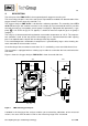
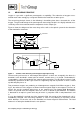
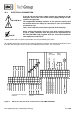
All possible electrical connections are placed inside the connector box below the analyser’s hou s-
ing. After loosening the cover screws, the following terminal items are accessible:
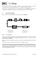
Figure 5 Electrical connection in the connection box of the PMA 50EX EEX e
L
1
1%
2
3%
3
10%
4
30%
5
100%
6
com
7
0
8
1%
9
3%
10
10%
11
30%
12
100%
N
13
0
14
0
15
+
16
0
17
+
18
0
19
NC
20
MC
21
NO
22
IN
23
0
24
external measuring range
selection
external measureing range
indication
Recorder outlet mA +
Recorder outlet mA 0
Recorder outlet V +
Recorder outlet V 0
Outlets
dc-isolated
0 or 4-20mA for
measuring range
0 - 10V
for 0 -100% O2
Power IN L
Power IN N
Status
contact
PE
Power IN PE
Option zero suppression ON