Operating Manual Oxygen Analyser Series PMA Version PMA 50 Ex Gas sampling and gas conditioning technology 9-3.
Dear customer, we have made up this operating manual in such a way that all necessary information about the product can be found and understood quickly and easily. Should you still have any question, please do not hesitate to contact M&C directly or go through your appointed dealer. Respective contact addresses are to be found in the annexe to this ope rating manual. Please also contact our homepage www.mc-techgroup.com for further information about our products.
List of Contents 1 2 3 4 5 6 7 8 General information .........................................................................................................5 Declaration of conformity ................................................................................................5 Electrical standards .........................................................................................................6 Safety instructions ............................................................................
List of Illustrations Figure Figure Figure Figure Figure Figure Figure Figure Figure Figure Figure Figure Figure 1 2 3 4 5 6 7 8 9 10 11 12 13 Figure 14 Figure 15 Figure 16 Figure 17 PMA 50 Ex Oxygen Analyser ................................................................................. 12 Scheme of the measuring cell and optical signal processing .................................. 15 Gas flow diagram ..................................................................................................
Head Office M&C TechGroup Germany GmbH Rehhecke 79 40885 Ratingen Germany Telephone: 02102 / 935 - 0 Fax: 02102 / 935 - 111 E - mail: info@mc-techgroup.com www.mc-techgroup.com 1 GENERAL INFORMATION The product described in this operating manual has been examined before delivery and left our works in perfect condition related to safety regulations.
3 ELECTRICAL STANDARDS The electrical standard of electrical equipment corresponds to the safety regulations concerning the EN61010 and to the safety requirements of the European standards EN 61508; EN 50014 : 1997, EN 50018 : 2000, EN 50019 : 2000, EN 50020 : 2002 and EN 50284 : 1999 for operation of the equipment in hazardous areas group II category 2. Attention must be paid to the Certificate of Conformity KEMA 03 ATEX 2215X (see appendix).
5 INFORMATION AND SAFETY INSTRUCTIONS FOR USING THE ANALYSER IN HAZARDOUS AREAS The Oxygen Analyser PMA 50 Ex is suitable for use in hazardous area group II category 2. The explosion proof protection is: II 2G EEx de IIC T5 or II 1/2 G EEx de [ia] IIC T5 KEMA (appr.-no.: 03 ATEX 2215X) The analyser has been certified through KEMA, authorized company for official approval of electric equipment in the Netherlands. Detailed information and a copy of the certificate are attached to this operating manual.
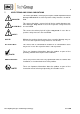
7 USED TERMS AND SIGNAL INDICATIONS DANGER! This means that death, severe physical injuries and/or important material damages will occur in case the respective safety measures are not fulfilled. WARNING! This means that death, severe physical injuries and/or important material damages may occur in case the respective safety measures are not fulfilled. This means that minor physical injuries may occur in case the respective safety measures are not fulfilled.
8 INTRODUCTION 8.1 SERIAL NUMBER The type plate with the serial number is fixed on the left side of the analyser’s housing. Please indicate always this serial number in case of questions or when purchasing spare parts. 8.2 POWER SUPPLY The internal power supply of the Oxygen Analyser PMA 50 Ex is reversible 115/230V AC, with 40Hz to 60Hz. Exact indications are to be found on the type plate. Variations of the power supply of -15% to +10% do not effect the function of the analyser.
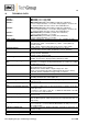
10 TECHNICAL DATA Part Number 05A1000 : 05A1000a : 05A2500 : 05A2500a 05A2505 : 05A2505a : Power supply Electrical connections Measuring ranges External range indication Remote range selection Combined analogue/digital indicator Output signals Response time for 90% FSD Accuracy after calibration Reproducibility PMA 50 EX, power supply 230V PMA 50 EX, power supply 115V PMA 50 EX/P/PD-1-50, power 230V, (not with SIL-certification) pressure compensation 0,6 - 1,5 bar abs.
Temperature cutoff Ambient temperature Storage temperature Medium touched material Connections measuring gas Flow failure Status signal outlet Housing / colour Dimensions/Weight Classification/Protection Certificate No. 10.1 Part number 05A9015 05A9005 05A9000 90A0009 90A0006 at 72°C via thermal fuse, non-reversible During operation between -10° C to + 50° C -20°C to +60°C at relative air moisture of 0-90% r.h. Platine, glass, PTFE, PVDF, stainl. steel 1.
11 DESCRIPTION The main part of the PMA 50 Ex is the magneto-dynamic oxygen measuring cell. This measuring principle is one of the most precise quantitative methods for determination of the oxygen contents in the range of 0-100 Vol.% O2. The Oxygen Analyser PMA 50 Ex is destined for stationary operation. The mounting into a EEx de IIC T5 housing 1 with ventilate arrestors in the sample gas inlet and outlet 6 makes it possible to install the analyser in hazardous area of group II category 2.
Every operational control is accessable from outside and guarantees a simple an d user-friendly handling during calibration and change-over of the measuring range. The operational controls are: Adjustment of measuring range span value 10, Range switch 11 and Adjustment zero point 12. The oxygen display of the PMA 50 Ex is effected by a two-scale analogue instrument 2, with ranges of 0-30 Vol% and 0-100 Vol % O 2. A digital display 3 is integrated into the analogue display.
11.2 PMA 50 EX/P/PD WITH PRESSURE COMPENSATION (WITHOUT SILCERTIFICATION) In case of barometric or process originated pressure variations, the PMA 50 Ex can be equipped with a special pressure compensation. The compensation can be effected within a pressure range of 0,6 – 1,1 bar abs.. Thereby errors in measurement caused by pressure variations can be eliminated. 11.
12 MEASURING PRINCIPLE Oxygen is a gas with a significant paramagnetic susceptibility. The molecules of oxygen are attracted much more strongly by a magnetic field than the molecules of other gases. The measuring principle shown in the following is benefitting from these characteristics of the oxygen. The great advantage of the paramagnetic measuring principle is the highly reduced cross sensitivity of the measurement to other components in the sample gas.
Every change of the oxygen concentration produces a lineary proportional change of the compensation current and can be read directly in % O 2 as oxygen value on the display . Due to its very small stagnant volume (2 cm 3) and the direct flow of the M&C measuring cell, an extremely fast response time (T 90-time) of 1 second for a high gas flow can be realized. 13 GAS FLOW DIAGRAM Figure 3 shows the gas flow diagram of the Oxygen Analyser PMA 50 Ex.
Figure 4 shows the construction of the conditioning system according to above mentioned spec ification.
14 RECEIPT OF GOODS The analyser PMA 50 Ex is a completely pre-installed unit. Please take the analyser and possible special accessories carefully out of the packaging mat erial immediately after arrival, and compare the goods with the items listed on the packing list ; Check the goods for any damage caused during delivery and, if necessary, notify your tran sport insurance company without delay of any damage discovered.
16 SUPPLY CONNECTIONS 16.1 SAMPLE GAS INLET AND SAMPLE GAS OUTLET The sample gas inlet and outlet are placed on the lower side of the analyzer. Both are equipped with ventilate arrestors type MC 95 A. The certified ventilate arrestors are executed with 1/4“ NPT inside thread. WARNING! The Ex-approval of the oxygen analyser is only valid in connection with the approved ventilate arrestors.
16.3 ELECTRICAL CONNECTION WARNING! NOTE! If you do not use the correct supply voltage, the equipment may be destroyed. Please take care of the correct supply voltage as indicated on the type plate. The equipotential bonding terminals of the analyser housing and the terminal box must always be connected in case of installation in hazardous area.
17 STARTING UP The following steps have to be executed when starting up the analyser: Before starting the equipment for the first time, check that the electrical connections and the gas connections have been executed as requested. The voltage indicated on the type plate must correspond to the mains supply. Any zero point deviation of the analogue display can be set right via the adjusting screw below the digital dispay.
18.1 ZERO CALIBRATION The calibraiton of the zero point is to be effected with a gas free of oxygen, eg. Nitrogen (N 2) 5.0. The following steps have to be executed: Connect the flexible PVC or Viton tube with the bottle’s pressure reducer of the N 2-zero gas bottle; WARNING! The pressure reducer should have a maximum outlet measuring range of 0-1,5 bar abs. and should always be adjusted to a low outlet pressure of max. 0,1 bar.
Shut the output valve of the pressure regulator and bottle valve and separate the tube conne ction to the analyser. After zero calibration the span has to be calibrated too. NOTE! 18.2 SPAN CALIBRATION NOTE! In case the oxygen concentration of the sample gas is below 30% O2, the calibration can be effected with dry air. Should the concentrations be higher, ideally, the test gas should correspond to the span value ! Before calibrating the span value, always check the zero point.
Wait approx. 30 seconds until the display is stable. If necessary, adjust the O 2-value of the test gas via the span potentiometer 10 (figure 1) (with a screw driver at air 20,93%); Check the analog output signals; The signal to be measured can be calculated as follows: (max. signal output - min. signal output) x Concentration [%] Measured value = + min.
19 MEASURING For the first starting up at a new location, the afore mentioned steps have to be performed. The interval of the new calibration is defined by the requirements of precision. After having chosen the desired measuring range, the analyser is ready to operate. DANGER! The sample gas must be free from all liquid or solid particles, i.e. the dew point of the gas must be significantly below the equipment temperature so that no condensate will occur inside the equipment.
20 CROSS SENSITIVITIES The following table shows the cross sensitivities of the most important gases at 20°C and 50°C. All values are based on a zero calibration with N 2 and a span calibration with 100 Vol.% O 2. The deviations are each valid for 100 Vol.% of the respective gas.
The selectivity of the above mentioned measuring principle is based on the high susceptibility of oxygen to other gases (see table). The following examples shall show how cross sensitivities can be considered for the zero calibr ation. Example 1: Determination of the rest content of oxygen in a 100% carbon dioxide (CO 2) protective atmosphere at 20°C In the table of cross sensitivities you can read the value for CO 2 at 20°C of –0,27.
The correction factor is calculated as follows: 100 Correction factor = (100 – O2-concentration) It is incidental: 100 = 1,0526 (100 – 5) For the gas mixture the rectified sum cross sensitivity then is calculated in good approximation for 0 Vol.% oxygen: 1,0526 x -0,1123 Vol.% = -0,1182 Vol.% The rectified sum cross sensitivity with change of sign now can be used for the correction of the zero calibration. In this case zero had to be adjusted at +0,12 Vol.%.
For the gas mixture in example 2 the rectified sum cross sensitivity then is calculated in good approximation for 20,93 Vol.% oxygen: 0,7907 x -0,1182 Vol.% = -0,0935 Vol.% The rectified sum cross sensitivity with change of sign now can be used for the correction of the span calibration. In this case span has to be adjusted at: 20,93 Vol.% + 0,0935 Vol.% = 21,02 Vol.%. 21 CLOSING DOWN In case of a short time closing down of the process control system, the analyser should remain „ON“.
The preceding components necessary for the sample gas conditioning are to be maintained a ccording to the respective operating manuals. The calibration of zero point and span value is to be effected with the corresponding test gases according to instruction. Recommended interval of calibration for standard applications: 1 x per week. 23.1 REMOVAL OF THE MEASURING CELL Figure 6 shows the schematic internal construction of the analyser PMA 50 Ex.
For dismounting the measuring cell, the following procedure is recommended: WARNING! For any work with the analyser it must be ensured that the ambience as well as the analyser itself are free from explosive or flammable gases ! NOTE! WARNING! Dangerous voltage.
Pull off the green 2-, 3- and 4-pole plug-in connections from the power supply board; Loosen the earth connection (green-yellow) of the transmitter unit (3 see figure.6); Loosen the hex screws 4 (see figure 6) on the top of the transmitter mounting plate; Loosen union nuts 1 at sample in- and outlet 7 (see figure 6); Now, the complete transmitter unit can be taken out of the housing. All further procedures should be executed on a clean work bench outside the hazardous area.
23.2 MECHANICAL ZERO POINT ADJUSTMENT The mechanical zero point adjustment has to be done as described in the following. 1 2 3 4 IR LED Temperature cut out (72°C) Sample gas heating coil Fastening screw photocell Figure 8 5 6 7 8 Heater element Adjustment screw photocell Measuring cell Photocell Schematic view of the transmitter unit Before switching on the analyser, set the range selector to 30%.
24 SPARE PARTS LIST The need of wearing and spare parts depends on the specific operating conditions. The recommended quantities of wearing and spare parts are based on experience and are not binding. O2 Analyser PMA 50 Ex (C) Consumable parts (R) Recommended spare parts (S) Spare parts Recommended piece number for use (years) C/R/S 1 2 3 Part-No.
25 APPENDIX Safety handbook according to SIL Circuit diagram front board PMA50ex 02.2010 Assembly front board PMA50ex 02.2010 Circuit diagram mains adapter PMA50ex 02.2010 Assembly / connection mains adapter PMA 50ex 02.
Safety handbook according to SIL Contemplated devices It was contemplated the PMA 50 EX with part no. 05A1000(a) and the following options: - Ventilation equipment and enclosure purging (part no. 05A9005 and 05A9000), Measuring cell solvant resistant or with glass solder (part no. 90A0009 u. 90A0006) Transmitter for measurements of gases from ex-zone 0 II 1/2 G EEx de [ia] IIC T5 Excluded are the PMA 50 EX/P/PD… with pressure compensation, part no.
Operating conditions Ambient conditions: Temperature: -10 °C bis +50 °C Pressure: 0.9- 1.1 bar abs. Vibrations have to be avoided. The sample gas has to be dry (dew point 5°C) and dust free and the sample gas inlet temperature is not allowed to exceed 50°C. The maximum inlet pressure is 1,1 bar abs. for the standard device and 1,5 bar abs. for devices with encosure purging or ventilation equipment. Generally a fine filter with min. 2µm has to be installed upstream.
Figure 9 Circuit diagram front board PMA50ex 10.2008 Gas sampling and gas conditioning technology 9-3.
Figure 10 Assembly front board PMA50ex 10.2008 Gas sampling and gas conditioning technology 9-3.
Figure 11 Circuit diagram mains adapter PMA50ex 10.2008 Gas sampling and gas conditioning technology 9-3.
Figure 12 Assembly / connection mains adapter PMA 50ex 10.2008 Gas sampling and gas conditioning technology 9-3.
Figure 13 Cut-out magnification front board for adjustment of temperature alarm (TP10, P19) (TP11: actual temperature) und flow alarm threshold (P20) Figure 14 Cut-out magnification front board couple sensor bridge for application of a transmitter without couple sensor Failure indication: B15: Flow-min, Flow-max failure B14: Transmitter LED-Strom failure B11: Transmittertemperatur max failure B12: Transmittertemperatur min failure B13: Powersupply +U B failure B10: Powersupply -UB failure (Couple se
Figure 15 Cut-out magnification front board for adjustment of reference voltage , amplification and offset of the O2-signal Gas sampling and gas conditioning technology 9-3.
Figure 16 Cut-out magnification mains adapter for adjustment of the temperature, current and voltage output Figure 17 Cut-out magnification mains adapter for adjustment of burden and limitation of the current output Gas sampling and gas conditioning technology 9-3.
Gas sampling and gas conditioning technology 9-3.
Gas sampling and gas conditioning technology 9-3.
Gas sampling and gas conditioning technology 9-3.
Gas sampling and gas conditioning technology 9-3.