
Operator's manual Instruction Manual

13
Gas sampling and gas conditioning technology 9-3.5.1-ME
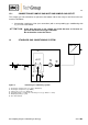
12.1 CONNECTION OF SAMPLE GAS INLET AND SAMPLE GAS OUTLET
The sample gas inlet and outlet are placed at the bottom side of the analyser and have tube con-
nections DN4/6mm.
Connect the sample gas inlet (rear connection) with a corresponding gas conditioning with
e.g. a PTFE hose DN4/6.
A T T E N T I O N
Avoid back pressure in the sample gas outlet because an increase of
pressure will distort the oxygen indication.
Do not bend the connection hoses.
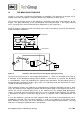
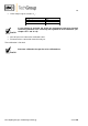
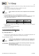
13 STANDARD GAS CONDITIONING SYSTEM
+5°C
PMA 20
Figure 5 Standard gas conditioning system
1 : Heated gas sample probe (e.g. probe SP2000-H)
2 : Heated gas sample line (e.g. 4M4/6)
3 : Sample gas cooler (e.g. ECM-1G)
4 : Peristaltic pump or condensate collecting vessel (e.g. SR25.1 or TG-1)
5 : Diaphragm pump (e.g. N3)
6 : Fine filter (FP-2T)