
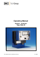
Operator's manual Instruction Manual

10
Gas sampling and gas conditioning technology 9-3.5.1-ME
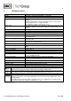
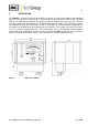
9.1 FRONT PANEL
1
Analog indication
4
Flow meter
2
Zero potentiometer
5
Needle valve 7 - 70 Nl/hr
3
Span potentiometer
6
Measuring range selector switch
7
LED - heating control
Figure 2 Front panel PMA20
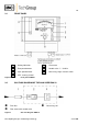
9.2 GAS FLOW DIAGRAM OF THE ANALYSER PMA 20
Fine filter Measuring cell
Flow meter with needle valve
Figure 3 Gas flow diagram PMA 10