Operating Manual Oxygen - Analyser Type PMA 20 Gas sampling and gas conditioning technology 9-3.5.
Content 1 2 3 4 5 6 General information ...................................................................................................................... 4 Declaration of conformity ............................................................................................................ 4 Safety instructions ........................................................................................................................ 5 Warranty ..........................................................
Dear customer, we have made up this operating manual in such a way that all necessary information about the product can be found and understood quickly and easily. Should you still have any question, please do not hesitate to contact M&C directly or go through your appointed dealer. Respective contact addresses are to be found in the annexe to this ope rating manual. Please also contact our homepage www.mc-techgroup.com for further information about our products.
HEAD OFFICE M&C TechGroup Germany GmbH Rehhecke 79 40885 Ratingen Germany Telephone: 02102 / 935 – 0 Fax: 02102 / 935 – 111 E - mail: info@mc-techgroup.com www.mc-techgroup.com 1 GENERAL INFORMATION The product described in this operating manual has been examined before delivery and left our works in perfect condition related to safety regulations. In order to keep this condition and to guarantee a safe operation, it is important to heed the notes and prescriptions made in this operating manual.
3 SAFETY INSTRUCTIONS Please take care of the following basic safety procedures when mounting, starting up or operating this equipment: Read this operating manual before starting up and use of the equipment. The information and warnings given in this operating manual must be heeded. Any work on electrical equipment is only to be carried out by trained specialists as per the reg ulations currently in force.
5 USED TERMS AND SIGNAL INDICATIONS DANGER! This means that death, severe physical injuries and/or important material damages will occur in case the respective safety measures are not fulfilled. WARNING! This means that death, severe physical injuries and/or important material damages may occur in case the respective safety measures are not fulfilled. This means that minor physical injuries may occur in case the respective safety measures are not fulfilled.
6 INTRODUCTION The M&C oxygen analyser PMA 20 is a temperature controlled instrument which has been designed for continuous measurements of oxygen concentrations in particlefree and dry sample gas. 6.1 SERIAL NUMBER The type plate with the serial number is in the lid of the analyser. Whenever you call M&C regarding questions or orders for the spares please give us the serial number of your PMA 20.
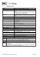
8 TECHNICAL DATA Oxygen analyser Series PMA Part No.
9 DESCRIPTION The PMA 20 is a reliable and easy-to-operate instrument. It is built into a compact wall mounting housing. The transducer unit maintains a constant operating temperature of 50 °C and a flashing LED on the control panel indicates the proper operating temperature of the analyser. The four measuring ranges are displayed on the analogue meter with 30/ 100% scale. Two output signals are available.
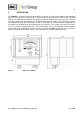
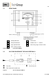
9.1 FRONT PANEL 1 Analog indication 4 Flow meter 2 Zero potentiometer 5 Needle valve 7 - 70 Nl/hr 3 Span potentiometer 6 Measuring range selector switch 7 LED - heating control Figure 2 9.2 Front panel PMA20 GAS FLOW DIAGRAM OF THE ANALYSER PMA 20 Fine filter Measuring cell Flow meter with needle valve Figure 3 Gas flow diagram PMA 10 Gas sampling and gas conditioning technology 9-3.5.
10 THE MEASURING PRINCIPLE Oxygen is a gas with a significant paramagnetic susceptibility. The molecules of oxy gen are attracted much more strongly by a magnetic field than the molecules of other gases. The measuring principle shown in the following is benefitting from these characteristics of the oxygen. The great advantage of the paramagnetic measuring principle is the highly reduced cross sensitivity of the measurement to other components in the sample gas.
Every change of the oxygen concentration produces a lineary proportional change of the co mpensation current and can be read directly in % O 2 as oxygen value on the display . Due to its very small stagnant volume (2 cm 3) and the direct flow of the M&C measuring cell, an extremely fast response time (T 90-time) of 1 second for a high gas flow can be realized. 11 RECEIPT OF GOODS AND STORAGE The analyser PMA 20 is a completely pre-installed unit.
12.1 CONNECTION OF SAMPLE GAS INLET AND SAMPLE GAS OUTLET The sample gas inlet and outlet are placed at the bottom side of the analyser and have tube connections DN4/6mm. Connect the sample gas inlet (rear connection) with a corresponding gas conditioning with e.g. a PTFE hose DN4/6. ATTENTION 13 Avoid back pressure in the sample gas outlet because an increase of pressure will distort the oxygen indication. Do not bend the connection hoses.
14 ELECTRICAL CONNECTION The electrical connection is done at the terminals in the connection box below the analyser: Loosen the two screws of the lid end remove it. CAUTION! False supply voltage can damage the equipment. When connecting the equipment, please ensure that the supply voltage is identical with the information provided on the model type plate! Power PE SW1 L Signal output 0 N 14.
16 After approximately 30 min. the LED in the indication instrument starts flashing. After 12 hours the transmitter has reached a temperature balance and the analyser is ready for c alibration. CALIBRATION The accuracy of an analyser mainly is dependent on its calibration. NOTE! Before calibration it has to be assured that the calibration conditions correspond to the conditions during measurement. The flow rate and the barometric pressure conditions have to be constant.
Check output signals at 0,0% O 2 : Output signal 0-1 V 0-20 mA 4-20 mA NOTE! Measurement 0V 0 mA 4 mA If a gas mixture is analysed, the single gas components have to be checked concerning potential cross sensitivity and regarded for zero calibration. (see chapter 16.1.1 and 16.1.2). Shut off pressure outlet valve and bottle valve. Disconnect hose connection from the analyser. Zero calibration is finished. After zero calibration the span has to be calibrated too.
16.1.1 CROSS SENSITIVITIES The following table shows the cross sensitivities of the most important gases at 20°C and 50°C. All values are based on a zero calibration with N 2 and a span calibration with 100 Vol.% O 2. The deviations are each valid for 100 Vol.% of the respective gas.
16.1.2 CONSIDERATION OF CROSS SENSITIVITIES The selectivity of the above mentioned measuring principle is based on the high susceptibility of oxygen to other gases (see table). The following examples shall show how cross sensitivities can be considered for the zero calibr ation. Example 1: Determination of the rest content of oxygen in a 100% carbon dioxide (CO2) protective atmosphere at 20°C In the table of cross sensitivities you can read the value for CO 2 at 20°C of –0,27.
The correction factor is calculated as follows: Correction factor = 100 (100 – O2-concentration) It is incidental: 100 = 1,0526 (100 – 5) For the gas mixture the rectified sum cross sensitivity then is calculated in good approximation: 1,0526 x -0,1123 Vol.% = -0,1182 Vol.% The rectified sum cross sensitivity with change of sign now can be used for the correction of the zero calibration. In this case zero had to be adjusted at +0,1182 Vol.%.
Connect the hose end of the instrument air or check gas bottle connection to the gas inlet of the analyser. Open the pressure reducer valve slowly, to avoid pressure peaks. Adjust the flow rate to 50 Nl/hr at the flow meter. NOTE! Always calibrate at the flow rate that is adjusted for the measurement too. Wait approximately 20 – 30 sec. until the indication has stabilised.
17 MEASURING For the first starting up at a new location, all steps in chapter 16 and 17 have to be performed. By the requirements of precision the interval of the new calibration can be carried out daily or weekly. CAUTION! The sample gas must be free from all liquid or solid particles, i.e. the dew point of the gas has to be below the equipment temperature so that no condensate will occur inside the equipment. If necessary, lower the dew point by means of a cooler or dryer.
21 SPARE PARTS LIST Wear, tear and replacement part requirements depend on specific operating conditions. The recommended quantities are based on experience and they are not binding. Oxygen analyser PMA 20 (C) Consumable parts (R) Recommended spare parts (S) Spare parts Part No.
Figure 7 Circuit diagram PMA 20 Gas sampling and gas conditioning technology 9-3.5.
Figure 8 Circuit diagram oxygen transducer unit PMA1.02.0 Gas sampling and gas conditioning technology 9-3.5.
Figure 9 Components list circuit diagram PMA1.02.0 Gas sampling and gas conditioning technology 9-3.5.
Figure 10 Components list circuit diagram PMA1.02.0 Gas sampling and gas conditioning technology 9-3.5.
Figure 11 Temperature sensor resistance dependent on temperature Gas sampling and gas conditioning technology 9-3.5.
Figure 12 Installation provisions and spare parts positions Gas sampling and gas conditioning technology 9-3.5.