
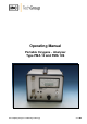
Operator's manual Instruction Manual

3
Gas sampling and gas conditioning technology 9-1.1-ME
List of Illustrations
Figure 1 Dimensions ...................................................................................................... 10
Figure 2 Front panel....................................................................................................... 11
Figure 3 Gas flow diagram PMA 10(S) ............................................................................ 12
Figure 4 Scheme of the measuring cell and optical signal processing.............................. 13
Figure 5 Standard gas conditioning system .................................................................... 15
Figure 6 Plug connection signal output ........................................................................... 16
Figure 7 Rear side ......................................................................................................... 17
Figure 8 PMA 10(S) with open housing ........................................................................... 25
Figure 9 Component buildup .......................................................................................... 27