
Operator's manual Instruction Manual

12
Gas sampling and gas conditioning technology 9-1.1-ME
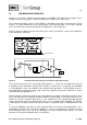
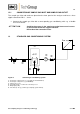
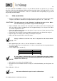
9.2 GAS FLOW DIAGRAM OF THE ANALYSER PMA 10(S)
1 Fine filter 3 Measuring cell
2 Flow meter with needle valve 4 Sample gas pump - Option
Figure 3 Gas flow diagram PMA 10(S)
9.3 OPTIONS
9.3.1 APPROVAL ACCORDING TO 13. AND 17. BIMSCHV AND TA-LUFT (NOT
FOR PMA 10S)
The approval happened by: Rheinisch-Westfälischer Technischer Überwachungs-Verein e.V. Es-
sen. These devices have the label " TÜV eignungsgeprüft" at the front side. In connection with
this approval a 4 -20 mA output is always necessary.
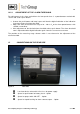
9.3.2 OUTPUT SIGNAL
For output signal 0 – 1V an output signal 0 – 20 or 4 – 20 mA is available as option. The 3-pole
connection bushing is provided on the front panel of the analyser.
9.3.3 RECHARGEABLE BATTERY
The analyser PMA 10(S) can be finished with a rechargeable battery. Hereby an operation off the
line is possible. The internal mains adapter than simultaneously is used as battery charger.
9.3.4 SAMPLE GAS PUMP
A sample gas pump with a capacity of 1 l/min – without pressure can be integrated in the device.
The pump is designed for short time rating only. For long-term operation an external sample gas
pump has to be be used.
9.3.5 ALARM CONTACT OUTLET (NOT FOR PMA 10S)
It is possible to adjust the alarm value via a potentiometer on the front panel to any value and it is
switched as a min. or max. contact. The outlet is a potential-free change over contact that is lead
through via a plug at the rear side.
Additionally an acoustic alarm with automatic or manual reset (30 sec.) is integrable.