
Operator's manual Instruction Manual

11
Gas sampling and gas conditioning technology 9-1.1-ME
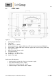
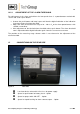
9.1 FRONT PANEL
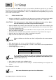
Figure 2 Front panel
1 Analog-/ digital-indication
2 Flow meter
3 Needle valve 7 – 70 Nl/hr
4 Alarm potentiometer – option (PMA 10) or LED active measuring range (PMA 10S)
5 Alarm-button – option (PMA 10) or switch for suppressed measuring range (PMA 10S)
6 Span potentiometer
7 Measuring range selector switch
8 Zero potentiometer
9 Sample gas - In DN 11-4 mm
10 Sample gas - Out DN 11-4 mm
11 Signal - Out 3-pole
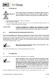
At the rear side there are:
Low heat device socket with 2 fine fuses for power supply
Push button for battery check - Option
Switch for the sample gas pump - Option
3 pole bushing for alarm contact outlet - Option