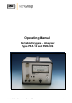
Operating Manual Portable Oxygene - Analyser Type PMA 10 and PMA 10S Gas sampling and gas conditioning technology 9-1.
Content 1 2 3 4 5 6 General information ................................................................................................................. 5 Declaration of conformity ........................................................................................................ 5 Safety instructions................................................................................................................... 6 Warranty .........................................................................
List of Illustrations Figure Figure Figure Figure Figure Figure Figure Figure Figure 1 2 3 4 5 6 7 8 9 Dimensions ...................................................................................................... 10 Front panel....................................................................................................... 11 Gas flow diagram PMA 10(S) ............................................................................ 12 Scheme of the measuring cell and optical signal processing....
Dear customer, we have made up this operating manual in such a way that all necessary information about the product can be found and understood quickly and easily. Should you still have any question, please do not hesitate to contact M&C directly or go through your appointed dealer. Respective contact addresses are to be found in the annexe to this ope rating manual. Please also contact our homepage www.mc-techgroup.com for further information about our products.
HEAD OFFICE M&C TechGroup Germany GmbH Rehhecke 79 40885 Ratingen Germany Telephone: 02102 / 935 – 0 Fax: 02102 / 935 – 111 E - mail: info@mc-techgroup.com www.mc-techgroup.com 1 GENERAL INFORMATION The product described in this operating manual has been examined before delivery and left our works in perfect condition related to safety regulations.
3 SAFETY INSTRUCTIONS Please take care of the following basic safety procedures when mounting, starting up or operating this equipment: Read this operating manual before starting up and use of the equipment. The information and warnings given in this operating manual must be heeded. Any work on electrical equipment is only to be carried out by trained specialists as per the regulations currently in force.
5 USED TERMS AND SIGNAL INDICATIONS D AN G E R ! This means that death, severe physical injuries and/or important material damages will occur in case the respective safety measures are not fulfilled. WARNING ! This means that death, severe physical injuries and/or important material damages may occur in case the respective safety measures are not fulfilled. This means that minor physical injuries may occur in case the respective safety measures are not fulfilled.
6 INTRODUCTION The portable M&C oxygen analyser PMA 10(S) is an non-thermostated instrument which has been designed for continuous and discontinuous measurement of oxygen concentrations in dry and particle-free sample gases. 6.1 SERIAL NUMBER The type plate with the serial number is on the back side of the analyser. Whenever you call M&C regarding questions or orders for the spares please give us the serial number of your PMA 10(S).
8 TECHNICAL DATA Oxygen analyser Series PMA Part No.
9 DESCRIPTION The PMA 10 is a reliable and easy-to-operate instrument and immediately operable. The lightweight instrument is built into a portable housing. The four measuring ranges are displayed on the analogue meter with 30% and 100% scale and the 100% O 2 range also on the digital meter. One output signal 0-1V is available as standard. Sample gas connections as well as a connector for the output signal are located on the front panel of the analyser.
9.
9.2 1 2 GAS FLOW DIAGRAM OF THE ANALYSER PMA 10(S) Fine filter Flow meter with needle valve Figure 3 9.3 9.3.1 3 4 Measuring cell Sample gas pump - Option Gas flow diagram PMA 10(S) OPTIONS APPROVAL ACCORDING TO 13. AND 17. BIMSCHV AND TA-LUFT (NOT FOR PMA 10S) The approval happened by: Rheinisch-Westfälischer Technischer Überwachungs-Verein e.V. Essen. These devices have the label " TÜV eignungsgeprüft" at the front side. In connection with this approval a 4 -20 mA output is always necessary.
10 THE MEASURING PRINCIPLE Oxygen is a gas with a significant paramagnetic susceptibility. The molecules of oxygen are a ttracted much more strongly by a magnetic field than the molecules of other gases. The measuring principle shown in the following is benefitting from these characte ristics of the oxygen. The great advantage of the paramagnetic measuring principle is the highly reduced cross sensitivity of the measurement to other components in the sample gas.
Every change of the oxygen concentration produces a lineary proportional change of the co mpensation current and can be read directly in % O 2 as oxygen value on the display . Due to its very small stagnant volume (2 cm 3) and the direct flow of the M&C measuring cell, an extremely fast response time (T 90-time) of 1 second for a high gas flow can be realized. 11 RECEIPT OF GOODS AND STORAGE The analyser PMA 10(S) is a completely pre-installed unit.
12.1 CONNECTION OF SAMPLE GAS INLET AND SAMPLE GAS OUTLET The sample gas inlet and outlet are placed on the front panel of the analyser and have a hose nipple connection DN 11 – 4 mm. Connect the sample gas inlet with a corresponding gas conditioning with e.g. a flexible PVC hose DN4/6. Avoid back pressure in the sample gas outlet because an increase of pressure will distort the oxygen indication. Do not bend the connection hoses.
14 ELECTRICAL CONNECTION WARNING ! False supply voltage can damage the equipment. When connec ting the equipment, please ensure that the supply voltage is identical with the information provided on the model type plate! At the rear side there is the low heat device socket. A 2m connection cable with low heat device connector and earthing type plug is included in the scope of delivery. 14.
14.2.1 ADJUSTMENT OF THE ALARM THRESHOLD For adjustment of the alarm treshold on the front panel there is a potentiometer marked with “alarm” and aside a push-button: Actuate the push-button and keep it pressed. Now the digital indication of the indication instrument shows the alarm threshold. Adjust the alarm threshold in the range of 0 – 100 % O2 at the alarm potentiometer with suitable screw driver. After adjustment of the desired alarm threshold release push button.
16 STARTING UP WARNING ! Check electrical connections and gas connections. Switch on mains voltage. Turn measuring range selection switch from „0“ to the desired measuring range. The analyser is ready for operation immediately. CAUT ION! 16.1 False supply voltage can damage the equipment.
For span calibration with M&C O2-analysers it is possible to abandon on special test gas mixtures because of the measuring principle and the linear measuring ranges. Dry and clean air is sufficient. For measurement concentrations > 40% O 2 a calibration with corresponding test gas could be possibly recommandable. 17.1 ZERO CALIBRATION Connect a flexible PVC- or FEP-hose with the pressure reducer of the N2-zero-gas bottle. The pressure reducer should have an output control range of max.
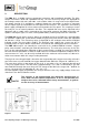
17.1.1 CROSS SENSITIVITIES The following table shows the cross sensitivities of the most important gases at 20 °C and 50°C. All values are based on a zero calibration with N 2 and a span calibration with 100 Vol.% O 2. The deviations are each valid for 100 Vol.% of the respective gas.
17.1.2 CONSIDERATION OF CROSS SENSITIVITIES The selectivity of the above mentioned measuring principle is based on the high suscep tibility of oxygen to other gases (see table). The following examples shall show how cross sensitivities can be considered for the zero calibr ation. Example 1: Determination of the rest content of oxygen in a 100% carbon dioxide (CO2) protective atmosphere at 20°C In the table of cross sensitivities you can read the value for CO 2 at 20°C of –0,27.
The correction factor is calculated as follows: Correction factor = 100 (100 – O2-concentration) It is incidental: 100 = 1,0526 (100 – 5) For the gas mixture the rectified sum cross sensitivity then is calculated in good approximation : 1,0526 x -0,1123 Vol.% = -0,1182 Vol.% The rectified sum cross sensitivity with change of sign now can be used for the correction of the zero calibration. In this case zero had to be adjusted at +0,1182 Vol.%.
NO T E ! Always calibrate at the flow rate that is adjusted for the measurement too. Wait approximately 20 – 30 sec. until the indication has stabilised. If necessary adjust span accurately according to the check gas concentration with a screw driver at the span potentiometer in the front panel. In case of air e.g. to 20,9 % O2.
19 CLOSING DOWN In case of a short time closing down of the the analyser no further precautions are required. In case of a closing down of the analyser for a longer period, it is recommended to flush the an alyser with dry and clean inert gas (eg. surrounding air) in order to prevent a d amage of the measuring cell by aggressive and corrosive liquid gases. For analyser with option rechargeable battery it is recommended for short or long term closing down to remain the analyser at the mains.
1 2 3 4 Quick-opening screw O 2-transmitter-unit Filter body Filter element clamp Figure 8 21 5 6 7 Filter element Filter head with filter inlet Connection hose gas IN to filter PMA 10(S) with open housing TROUBLE SHOOTING Error Possible reason Check/Repair No indication No supply voltage Check supply voltage according to type plate. Check wether mains cable is plugged in accurate. Check fine fuse in the low heat device socket.
22 SPARE PARTS LIST Wear, tear and replacement part requirements depend on specific operating conditions. The recommended quantities are based on experience and they are not binding. Oxygen analyser PMA 10(S) (C) Consumable parts (R) Recommended spare parts (S) Spare parts Part No.
Figure 9 Component buildup Gas sampling and gas conditioning technology 9-1.