-1- Instruction manual Microprocessor controlled oxygen analyser PMA Version PMA100-L 9-3.12.
-2- Table of content 1. Electrical standards 3 2. Important safety informations 3 3. Warranty 3 4. Used terms and signal indication 4 5. Introduction 4 5.1 Analyser model ............................................................................................................................ 4 5.2 Patent references .......................................................................................................................... 4 5.3 Serial number ............................
-3- 1. Electrical standards The electrical standard corresponds to the safety regula– tions concerning the low-voltage recommendation 73/23 EWG in version 93/68 EWG and the recommendation of electromagnetic compatibility 89/336 EWG in version 93/68 EWG. We meet the following standards: EN 61010 part 1 / EN 50081 part 1 / EN 50082 part 1 EN 55014 / EN 60555 part 2 & 3 / EN 60335 part 1 2.
-4- 4. Used terms and signal indication SKILLED STAFF These are persons with necessary qualification, who are familiar with installation, use and maintenance of the product. The signals are used according to DIN 4844 and EU Recommendation 91/C53/06. These are important informations about the product or parts of the instruction manual which require user’s attention. 5. Introduction 5.1 Analyser model The Oxygen analyser type PMA100-L is produced by M&C Products Analysentechnik in Ratingen, Germany. 5.
-5- 6. Application The transducer of the PMA100-L works at a stable temperature of +55°C. Therefore the analyser is suitable for continuous measurements of oxygen concentrations in particlefree and dry sample gases. Safe operation, reliability and minimized maintenance are the characteristic of the PMA100-L.
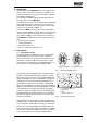
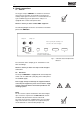
-6- 1 1: 2: 3: 4: 5: 6: Fig. 3: Measuring cell „LED“ light beam Photo cell Feed back amplifier Output amplifier Meter indication 2 ➞ ➞ Principle of operation 3 4 5 6 the corresponding output of the amplifier, which is a current and also proportional to the oxygen content, produces a magnetic field in the feedback coil opposing the forces and thereby causing the dumb bell to rotate.
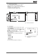
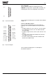
-77.3 Dimensions and weight The analyser is build in a 19” housing, also suitable for table mounting. Fig. 5 shows the dimensions of the PMA100-L. Please take additional 60mm fitting-depth into consideration when installing the analyser. The weight of the analyser is approx. 11 kg. 483 (84HP) 341 465 50 10 20,9 V0l.% O2 1010 mbar 177 (4U) Alarm 7 102 ⇑ ⇓ PMA100 440 Fig. 5: 7.4 Front panel The following figure shows the front panel of the oxygen analyser PMA100-L.
-87.5 Part No. Technical data 03A3100(a): PMA100-L, power supply 230 VAC, 50 Hz, 115 VAC, 60 Hz signal: 4-20 mA; (a)=115 V Measuring ranges 4 linear measuring ranges free selectable, lowest span 1%, basis parameterizing: 0-2,5; 0-10; 0-25; 0-100 Vol.% O2 *; manual, automatic or remote range control and range indication is possible Indication, suitable in German, English and French 2 line, 16-sign. LCD-display, resolution 0,01 Vol.
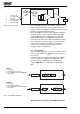
-9- 8. Supply connections 8.1 Medium The oxygen analyser PMA100-L is suitable for continuous measurements of oxygen concentrations in particle-free and dry sample gases. Therefore it is recommended to use a gas conditioning system upstream the analyser, f.e. equipped with a cooler and a particle filter. We like to inform you about suitable M&C equipment. The following diagram shows the connections on the back panel of the PMA100-L.
- 10 - mA + 1 2 3 4 5 6 7 mA - Fig. 8: 8 9 10 11 12 13 14 15 15-pole Sub-D socket X3 1 Out 4 MC 2 Out 3 NO 3 4 Out 2 MC 5 Out 1 NO 6 Alarm MC 7 Status MC 8 Out +24V 9 IN 1,2,4; GND 10 IN 3 (+24V) 11 In 1 (+24V) 12 In 4 (+24V) 13 Fig. 9: 8.2.1 mA output The mA output is available on the back panel of the PMA100-L (see fig.8) at the 15-pole Sub-D socket X3. The following figure shows the configuration of the terminal.
- 11 - 9. Receipt and storage The PMA100-L is completely pre-installed and normally delivered in one packaging unit. • Please take the analyser and possible special accessories carefully out of the packaging material immediately after arrival, and compare the goods with the items listed on the delivery note; • Check the goods for any damage caused during delivery and, if necessary, notify your transport insurance company without delay of any damage discovered.
- 12 - 12.Menu description 12.1 • Table of content Overview menu-drive and Overview operating keys ........................................................... 13 12.2 Warming up ..................................................................................................................................... 14 12.3 Alarm log-book ............................................................................................................................... 14 12.4 Parameterising level 1 ..........
- 13 - Overview menu-drive Overview operating keys Display Meas Status CAL Alarm log-book Entry code • Startup of measuring menu • Function: to leave the actual menu structure to the measuring display • Startup of calibration Select • Selection of menu points • Selection of changeable positions Enter • Jump into submenu • Confirmation of input ↑↓ • Selection of submenu points if shown on the display Code 1 Code 2 Read only CAL Language LCD contrast see code1 Zerogas concentration Mea
- 14 - MC Para O2 V.... TM M&C Products press: 1005 mbar ⇑ ⇓ press: 1005 mbar heating 22.5°C Select 12.2 Warming up After switching on the analyser type PMA100-L, the warming-up begins. The following display appears for approximately 20 seconds: • M&C logo • current O2-concentration • Software-version implemented in the PMA100-L • and the trademark. After further 20 seconds the display changes.
- 15 Parameterising level 1 The Select key leads to the next menu point. 12.4.3 Set range The desired ranges 1 to 4 or the autorange are selected by the Direction keys ⇑⇓ . The display is opened for changes by the Enter key. The first changeable position is underlined and can be changed operating the Direction keys ⇑⇓ . A jump to the next position happens via the Select key. The entry of the complete measuring range has to be confirmed by the Enter key.
- 16 A selection is done by the Direction keys ⇑⇓ and confirmed by the Enter key. Enter Select The Select key leads to the next menu point. ↑ ↑ status error mA no, 0mA, 2mA, 20,5mA, ... ⇑ ⇓ Enter Select 12.4.7 Set date/time The Enter key enables the entry of the date/time values: first month, day and year, then hour and minute. The first changeable position is underlined and can be changed operating the Direction keys ⇑⇓ . A jump to the next position happens via the Select key.
- 17 An alarm situation can be kept. If yes, one input must be configured as a reset (see 12.4.9). The entry starts with the Enter key. The first changeable position is underlined and can be changed operating the Direction keys ⇑⇓ . A jump to the next position happens via the Select key. The entry has to be confirmed by the Enter key, and the Select Select key leads to the next menu point. Select 1:0 ⇓ ↑ input config. input 1...4 Enter ⇑ ⇓ ↑ input config.
- 18 - ↑ ↑ conc. alarm 1...4 [< or >] xx.xx% Enter Select ⇑ ⇓ ⇑ ⇓ Select • Display concentration alarm The following menu point determines whether a concentration alarm is displayed as: • alarm contact, • status contact, or • no. A selection happens via the Direction keys ⇑⇓, and is confirmed by the Enter key. If ‘no’ is selected, the alarm signal can be used as a relay control output (see 12.4.8). The Select key leads to the next threshold value.
- 19 12.5 Parameterising level 2 12.5.1 Step into the menu System parameters can be changed in level 2. Operating the MEAS key leads back to the configuration level. Operating two times the Select key leads from the measuring menu to the entry of the access code (see 12.2). Select Enter to config. Code: 0000 The Enter key opens the menu. The first changeable position is underlined and can be changed via the Direction keys ⇑⇓ . Operating the Select key jumps to the next position.
- 20 12.5.5 Current pressure The Enter key opens the display to change the value for the current pressure (normal pressure at the respective location). The modified pressure value is confirmed by the Enter key. current pressure .....mbar Enter Check current pressure value when carrying out zero and span calibration. Select The Select key leads to the next menu point. 12.5.6 Password • Change password level 1 The preadjusted password can be changed by a four-digit individual code.
- 21 12.6 Zero- and span calibration Operating the Cal key leads to the display represented beside. A jump into the entry mode of the zero calibration happens automatically. Cal zero conc. xx.xx%O2 12.6.1 Zero gas concentration Enter opens the display. The Direction keys ⇑⇓ operate the input of the zero gas concentration (cross sensitivities see chapter 13.2). The first changeable position is underlined and can be changed operating the Direction keys ⇑⇓ .
- 22 Select Select leads to the following menu point. 12.6.5 Calibration log-book It is possible to read back the data (date and time) of the last 9 calibrations via the Direction keys ⇑⇓ . cal. log-book M 10.11.99 11:o7 The kind of calibration is marked as follows: M manual calibration. A fault during the calibration is displayed as: E M 10.11.99 11:07 Select Select leads to the beginning of the calibration. 13.Calibration A calibration is recommended latest every 4 weeks.
- 23 Gas Formula + 20°C + 50°C Argon Ar - 0,23 - 0,25 Acetylene C2H2 - 0,26 - 0,28 Acetone C3H6O - 0,63 - 0,69 Acetaldehyde C2H4O - 0,31 - 0,34 Ammonia NH3 - 0,17 - 0,19 Benzene C6H6 - 1,24 - 1,34 Bromine Br2 - 1,78 - 1,97 Butadiene C4H6 - 0,85 - 0,93 Methyl propene C4H8 - 0,94 - 1,06 n-Butane C4H10 - 1,10 - 1,22 Chlorine Cl2 - 0,83 - 0,91 Hydrogen chloride HCL - 0,31 - 0,34 Nitrous oxide N2O - 0,20 - 0,22 Diacetylene (CHCl)2
- 24 Example : The residual oxygen percentage should be measured in a closed 100% carbon dioxide (CO2) atmosphere. The „zerocalibration“ is done by means of Nitrogen (N2). According to the list of cross-sensitivities the error for CO2 at 20°C is -0,27%. In order to obtain a higher accuracy this means for the calibration that the reading should be adjusted at +0,27% with N2, in order to compensate the error of CO2. Since the values of cross-sensitivities are based on 100 Vol.
- 25 - 14.Measuring The connections for sample gas inlet and outlet are located on the back panel of the PMA100-L oxygen analyser (see 8.1). A detailed description of the menu-driven handling is given in chapter 12. Note! The oxygen analyser PMA100-L is suitable for continuous measurements of oxygen concentrations in particle-free and dry sample gases. Therefore it is recommended to use a gas conditioning system downstream the analyser equipped with a cooler and a particle filter. 14.
- 26 - 15.Function of in- and output contacts and alarms The following in- and output contacts are available at the Sub-D socket X4 at the back panel of the analyser (specification see 8.2.2): • • • • 4 binary inputs, 4 relay output contacts, 1 common relay alarm contact, and 1 common relay status contact. The binary inputs can be reserved for the following funct– ions (configuration see 12.4.9): • external alarm: an external alarm signal, f.e.
- 27 The following alarm messages are available at the common alarm output: • concentration alarm 1 - 4 (if allocated, see above) Status messages like: • flow alarm, • transducer temperature, • hardware fault, and • leaving the current measuring range. are signalised via the alarm LED, the analyser display and the status contact output. Menu point 12.4.6 enables to identify a status fault via a permanent mA-output signal. It is available at the Sub-D socket X3 (see 8.2.1).
- 28 - 17.Maintenance and repair Before carrying out any maintenance or service activities, the engineer concerned must ensure that the analyser is disconnected from the electrical supply of power! • Maintenance of the analyser should be performed by qualified personnel, and the frequency of maintenance may vary as a result of operating experience. • Any used spare parts must be specified as M&C spare parts.
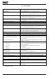
- 29 - 18.Trouble shooting Fault description Display Solution Measuring cell doesn‘t work properly at 100 Vol.-% (suppressed measuring range 99-100 Vol.-%) E:01 resp. F:01, depending on the language Give air resp. nitrogen to the analyser and restart the analyser Calibration fault:span gas is switched off while proceeding the calibration of the span. Measuring value always 0 Vol.
- 30 - 19.Spare part list Wear, tear and replacement part requirements depend on specific operating conditions. The recommended quantities are based on experience and are not binding. Oxygen Analyser Type PMA100-L (C) consumable parts (R) recommended spare parts (S) Spare parts recommended quantity PMA being in operation (years) Part.-No. Indication 90 A 0010 90 A 0015 Measuring cell PMC1 Flowmeter glass 7-70 Nl/hr C/R/S 1 2 3 S S - - 1 1 20.