
Operator's manual Manual
10
Gas sampling and conditioning technology 6-1.2.1ME
NOTE!
Pumps have mechanical moving parts that can induce vibrations.
To prevent damages at the pump or at peripheral components /
facilities as well as minimizing noise development an appropriate
vibration decoupling is necessary. For this M&C can deliver e.g.
anti-vibration pads.
This explicit is also valid for the connection of the sample lines at
the pump head.
10.1 MECHANICAL INSTALLATION
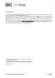
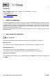
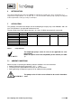
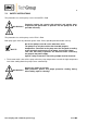
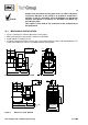
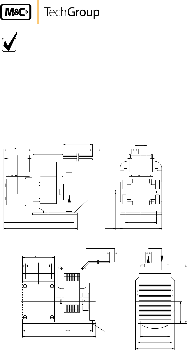
Figure 1 and figure 2 show the dimensions of the pumps.
When mounting the pump provide sufficient air ventilation.
Avoid acidents caused by the fan.
Install the pump at the highest place in the system and/or with the pump head showing down. This
avoids that condensate can be assembled inside the pump head.
43
900
8
68
40
113
G1/8“
18
7,2
48
64
4xM4
Figure 1 Dimensions (mm) N3/5 KPE
4xM4
Drehrichtung
52
900
8
G1/8“
22
74
40
119
48
57
64
95
6
31,5
Figure 2 Dimensions (mm) N9 KPE