Instruction Manual Diaphragm Pump series N Version N3 KPE, N3 KP18 N5 KPE, N5 KP18 N9 KPE, N9 KP18 Gas sampling and conditioning technology 6-1.2.
List of Contents 1 2 3 4 5 6 7 General information ............................................................................................................... 4 Declaration of conformity ...................................................................................................... 4 Safety instructions ................................................................................................................. 5 Warranty ...................................................................
Dear customer, we have made up this operating manual in such a way that all necessary information about the product can be found and understood quickly and easily. Should you still have any question, please do not hesitate to contact M&C directly or go through your appointed dealer. Respective contact addresses are to be found in the annexe to this operating manual. Please also contact our homepage www.mc-techgroup.com for further information about our products.
Head Office M&C TechGroup Germany GmbH Rehhecke 79 40885 Ratingen Germany Telephone: 02102 / 935 - 0 Fax: 02102 / 935 - 111 E - mail: info@mc-techgroup.com www.mc-techgroup.com 1 GENERAL INFORMATION The product described in this operating manual has been examined before delivery and left our works in perfect condition related to safety regulations. In order to keep this condition and to guarantee a safe operation, it is important to heed the notes and prescriptions made in this operating manual.
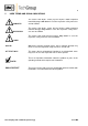
3 SAFETY INSTRUCTIONS Please take care of the following basic safety procedures when mounting, starting up or operating this equipment: Read this operating manual before starting up and use of the equipment. The information and warnings given in this operating manual must be heeded. Any work on electrical equipment is only to be carried out by trained specialists as per the regulations currently in force.
5 USED TERMS AND SIGNAL INDICATIONS DANGER! This means that death, severe physical injuries and/or important material damages will occur in case the respective safety measures are not fulfilled. WARNING! This means that death, severe physical injuries and/or important material damages may occur in case the respective safety measures are not fulfilled. This means that minor physical injuries may occur in case the respective safety measures are not fulfilled.
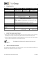
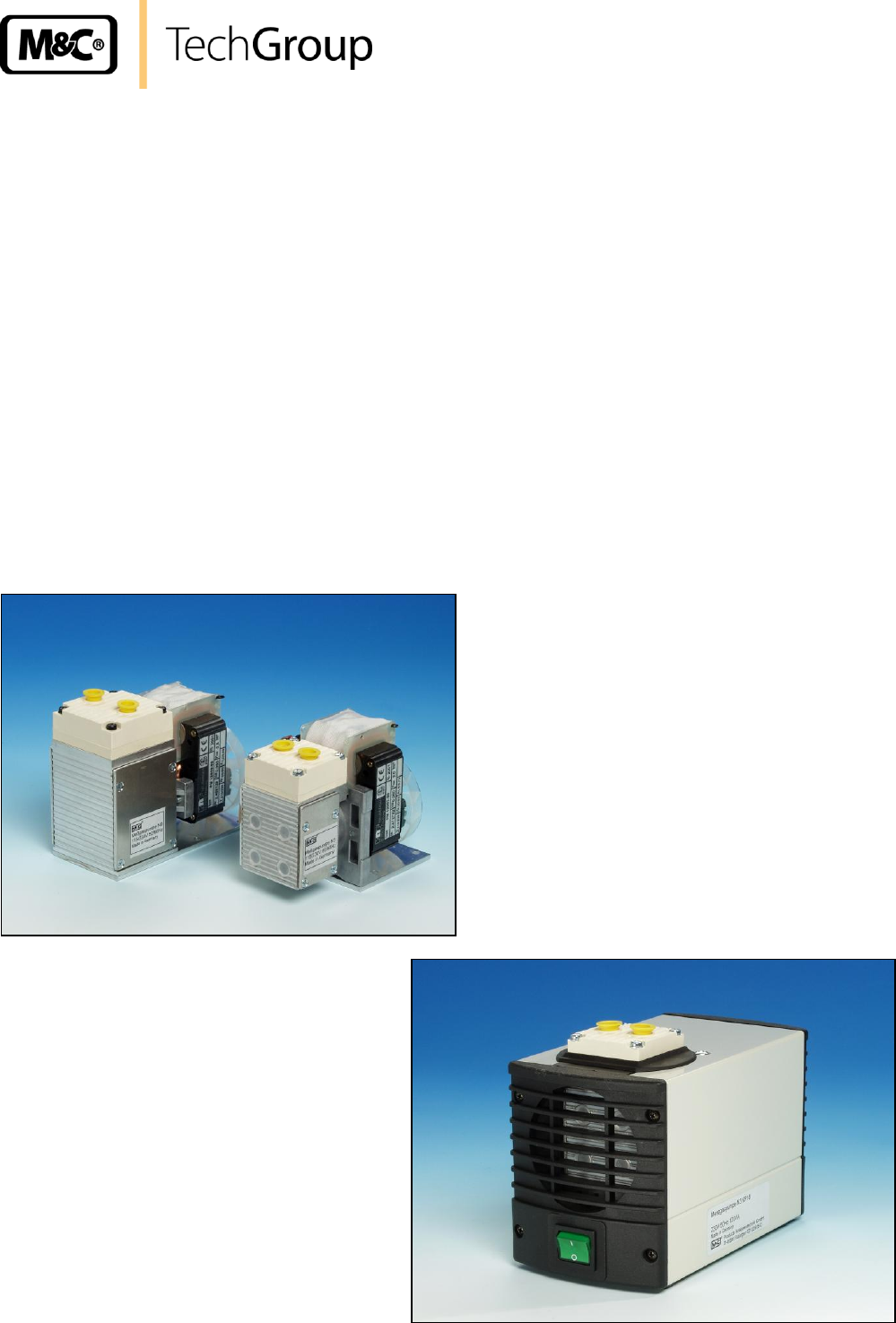
6 INTRODUCTION The compact diaphragm pumps type N3/5/9 are suitable for sampling air, gases and vapours in a temperature range between + 5 °C and + 40 °C. The construction and the pump capacity are adapted to the requirements of the gas analysis technique. 7 APPLICATION The sampling evacuation and compression of the diaphragm sample pump series N3/5/9 is 100% oilfree. The operation is gas-tight and maintenance-free. The noise level of the pump without housing is less than 55 dB(A).
7.2 SAFETY INSTRUCTIONS The protection class of the pumps series N3/5/9 KPE is IP00. WARNING! Protection against the contact with electrical and moving parts respectively the penetration of particles into the pump has to be provided externally. The protection class of the pumps series KP18 is IP20. Both pump types have no protection against water. Please provide protection before start-up. NOTE! Do not use pumps series N 3/5/9 in hazardous areas.
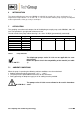
8 TECHNICAL DATA Diaphragm Pump Series Part Number Max. operating pressure N3 KPE / N3 KP18 N5 KPE / N5 KP18 N5 KPE / N5 KP18 02P3351 / 02P3006 02P3355 / 02P3007 02P3360 / 02P3008 0,25 bar – 3 bar abs. 3 Nl/min 0,15 – 3 bar abs. 0,15 – 1,5 bar abs. 5 Nl/min 9 Nl/min +5°C...+40°C +5°C...+40°C -15°C bis +60°C 230V/50Hz; 115V/60Hz 60W 60W Capacity at atm.
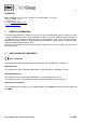
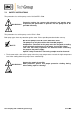
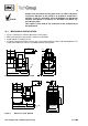
Pumps have mechanical moving parts that can induce vibrations. To prevent damages at the pump or at peripheral components / facilities as well as minimizing noise development an appropriate vibration decoupling is necessary. For this M&C can deliver e.g. anti-vibration pads. This explicit is also valid for the connection of the sample lines at the pump head. NOTE! 10.1 MECHANICAL INSTALLATION Figure 1 and figure 2 show the dimensions of the pumps.
G1/8“ 47 20 120 106 5 164 Figure 3 ca. 57 90 Dimensions (mm) N3/5 KP18 G1/8“ 51,5 29,5 132 5 Figure 4 187 ca. 57 90 Dimensions (mm) N9 KP18 Gas sampling and conditioning technology 6-1.2.
10.2 ELECTRICAL INSTALLATION When making the electrical installation the safety regulations must be observed. In particular make sure that the electricity supply is isolated before trying to connect the pump.. WARNING! NOTE! When connecting the equipment, please ensure that the supply voltage is identical with the information provided on the model type plate. The supply voltage is only allowed to deviate max. +6 % - 10% from the indication on the model type plate.
10.3 PNEUMATIC Remove the protection plugs from the port threads (thread size G1/8“). Accessories like hose connections are screwed into the port threads by sealing tape (using M&C connectors sealing tape is not necessary). Connect the suction and pressure lines. Arrange the suction and pressure lines so that condensate cannot run into the pump. NOTE! The pump must only be used in the conditions specified in the technical data.
12 STARTING Specific safety instructions for media being handled must be observed. Before pumping a medium, the compatibility of materials of pump head, diaphragm and valves with the medium must be checked (for pump materials: see table 1). The following steps should be carried out before initial start-up: The pump must not start against pressure or vacuum. When it is switched on the pressure in the suction and pressure lines must be atmospheric.
3 4 2 11 9 1 13 14 16 8 Figure 6 Sectional drawing N3/5 KPE Figure 7 Sectional drawing N9 PE 7 Parts and tools required: Valve plates, sealing rings (2 for each pump head) and structured diaphragm(s) Screwdriver no. 1 NOTE! Always change valve plates, diaphragm and sealing rings at the same time.
14.2 14.3 CHANGING THE DIAPHRAGM TYPE N 3/5/9 KPE/KP18 Turn the fan to bring the structured diaphragm 9 to top dead centre. Lift the edge of the diaphragm and gripping it on opposite sides unscrew it by turning anticlock-wise. Please take care that the diaphragm spacers 11 on the threaded portion of the diaphragm do not fall into the housing. Take the diaphragm spacer 11 off the threaded portion of the diaphragm and retain them.
WARNING! Aggressive medium possible. Wear protective glasses and proper protective clothing! For recommended spare parts please see Section 16. Gas sampling and conditioning technology 6-1.2.
15 TROUBLE SHOOTING Before working on the pump isolate the power supply securely, then check that the lines are not live. The following tips for fault-finding are best employed in the sequence shown. Problem/indication Pump produces no flow Flow, pressure or vacuum too low NOTE! Possible cause Action/Check No main supply. Check power supply. Check plug for correct fit. Thermal switch has opened due to over-heating. Connections or lines are blocked.
16 SPARE PARTS LIST Wear, tear and replacement part requirements depend on specific operating conditions. The recommended quantities are based on experience and are not binding.
17 APPENDIX Pump capacity of the diaphragm pump type N3...9 KPE/KP18 For further product documentation, please see our internet catalogue: www.mc-techgroup.com Gas sampling and conditioning technology 6-1.2.
Figure 8 Pump capacity N3/5 KPE/KP18 Figure 9 Pump capacity N9 KPE/KP18 Gas sampling and conditioning technology 6-1.2.