Operating Manual Diaphragm-sample pump series MP ® Version MP47, MP47/R, MP47-Z, MP47-Z/R, MP47/D Gas sampling and gas conditioning technology 6-1.1.
List of content 1 2 3 4 5 6 7 8 General information ................................................................................................................ 4 Declaration of conformity ....................................................................................................... 4 Safety instructions .................................................................................................................. 5 Warranty ...............................................................
Dear customer, we have made up this operating manual in such a way that all necessary information about the product can be found and understood quickly and easily. Should you still have any question, please do not hesitate to contact M&C directly or go through your appointed dealer. Respective contact addresses are to be found in the annexe to this operating manual. Please also contact our homepage www.mc-techgroup.com for further information about our products.
Head Office M&C TechGroup Germany GmbH Rehhecke 79 40885 Ratingen Germany Telephone: 02102 / 935 - 0 Fax: 02102 / 935 - 111 E - mail: info@mc-techgroup.com www.mc-techgroup.com 1 GENERAL INFORMATION The product described in this operating manual has been examined before delivery and left our works in perfect condition related to safety regulations. In order to keep this condition and to guarantee a safe operation, it is important to heed the notes and prescriptions made in this operating manual.
3 SAFETY INSTRUCTIONS Please take care of the following basic safety procedures when mounting, starting up or operating this equipment: Read this operating manual before starting up and use of the equipment. The information and warnings given in this operating manual must be heeded. Any work on electrical equipment is only to be carried out by trained specialists as per the regulations currently in force.
5 USED TERMS AND SIGNAL INDICATIONS DANGER! This means that death, severe physical injuries and/or important material damages will occur in case the respective safety measures are not fulfilled. WARNING! This means that death, severe physical injuries and/or important material damages may occur in case the respective safety measures are not fulfilled. This means that minor physical injuries may occur in case the respective safety measures are not fulfilled.
6 INTRODUCTION This diaphragm pump MP47 ... is suitable for corrosive gases. It is constructed especially for problems in the analysis technique. 7 DESCRIPTION The pump MP47 has a PTFE-head. All sample contacting parts are out of PTFE. The pump works absolutely lubricant free, so gases remain analytically unchanged. Due to a special diaphragm and valve system, the pump operates maintenance-free. The MP47 ...
8 AMBIENT CONDITIONS When the pump is operating the following ambient conditions must be maintained: • Ambient temperature during operating: -10 °C .... + 40 °C. • The pump must be protected from the effects of dust and water. • During operating an adequate supply of air for cooling must be provided. 8.1 SAFETY The protection class of the pumps MP47/MP47-Z is IP20 and so offer no protection against contact or foreign bodies.
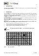
9 TECHNICAL DATA Diaphragm pump Part No. Power supply Degree of protection Capacity max.
10 VERSION MP47/R AND MP47-Z/R WITH INTEGRATED NEEDLE VALVE TYPE .../R FOR FLOW ADJUSTMENT The integrated needle valve in the pump head is an internal bypass and allows to adjust the flow capacity . In case of the optimal needle form, flow adjustment in a wide range is possible. All parts in contact with sample are made from PTFE and PVDF. No O-rings are necessary.
11 VERSION MP47 .../D WITH A DOUBLE DIAPHRAGM SAFETY SYSTEM/ DIAPHRAGM BREAKAGE MONITORING SYSTEM 11.1 APPLICATION There are some applications - for example when processing with strong aggressive, high toxic or hydrocarbon contaminated gases, it is necessary to install a high level safety system. For these applications, it is important to monitore continuously the tightness of the pump diaphragm. 11.2 DESCRIPTION M&C provides for the series MP47... pump as option a diaphragm breakage monitoring.
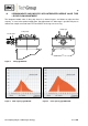
12 FLOW SENSOR LPH 125-1-A-SPST INCL. CONNECTION SET MP47 .../D MOUNTED ON PUMP MP47 .../D The optional available flow sensor LPH is provided with a mounting clip, 2x male connectors 1/8”- 2 mm and 0,5 m PTFE tube 1 x 2 mm. 51 LPH-7 l/hr ø 28 1/8“ NPT f Figure 6 Pump MP47 .../D with flow sensor Fitting position: vertical Alarm level: 7 l/hr Switching function: NC or NO depending on mounting position NC = lead of flow sensor in position at the top Contact rating: DC max. 200 V, 50 W, 1 A; AC max.
14 INSTALLATION INSTRUCTIONS When installing the pump make certain that accident prevention regulations and safety instructions including those for subsequent operation are observed. The safety instructions in section 6.2 must be observed. NOTE! The pump must only be used in the conditions specified in the technical data. The pump should be installed away from heat sources and freely ventilated to prevent any accumulation of heat.
Figure 7 14.2 Dimensions (mm) pump MP47.. ELECTRICAL When making the electrical installation the safety regulations must be observed. In particular make sure that the electricity supply is isolated before trying to connect the pump. The diaphragm pumps type MP47, MP47/R, MP47-Z, MP47-Z/R, MP47/D must not be used in hazardous areas. WARNING! NOTE! When connecting the equipment, please ensure that the supply voltage is identical with the information provided on the model type plate.
The pump must be installed so that contact with live parts (connections, possibly windings) is impossible. Figure 8 Electrical connection of the pump Unscrew the cover of the connection box with the PG cable glands; Put the cable through the cable gland and connect it according to figure 8; Connections are marked in the connection box. 14.3 PNEUMATIC Remove the protection plugs from the port threads (thread size G1/4”).
15 SUPPLY LINE CONNECTIONS 15.1 HOSE-/TUBE CONNECTIONS The gas inlet and outlet hoses/tubes are connected on the top of the pump. Standard G1/4" threaded joints are available for the connection of the gas sample lines. NOTE! The valve body must be fixed while mounting the fittings because moving may change the pump capacity.
If restriction or control of the air or gas flow is made on the pressure side ensure that the maximum permissible operating pressure is not exceeded. When the pump is at a standstill the inlet and exhaust must be at normal atmospheric pressure. Diaphragm and valve plates are the only parts subject to wear. Wear is usually indicated by a drastic reduction in the pneumatic performance. When replacing parts proceed as described in section 18. Ambient conditions: see technical data.
Valve, suction side Valve, pressure side Figure 9 Sectional drawing pump MP47 Parts and tools required: Valve plates and structured diaphragm (see spare part list , chapter 20) Always change valve plates, diaphragm and sealing rings at the same time. NOTE! Change the diaphragm and valve plates in the following sequence: 18.
Loosen the 4 screws M and remove the cover N ; Screw the new diaphragm K into the rod L hand-tight; Turn the flywheel P until the rod L is in a central position. Control that the bulge of the diaphragm K fits to the groove of housing A ; Fix the diaphragm head B and the pressure plate C according to the mark; Fix the 4 hexagon scews H constantly over cross until the plate springs R are flat; Turn the flywheel P and check whether it works proper; Mount the cover N ; 18.
For recommended spare parts please see section 20. 19 TROUBLE SHOOTING Before working on the pump isolate the power supply securely, then check that the lines are not live. The following tips for fault-finding are best employed in the sequence shown.
20 SPARE PARTS LIST Wear, tear and replacement part requirements depend on specific operating conditions. The recommended quantities are based on experience and they are not binding. Diaphragm pump MP47, MP47/R, MP47-Z, MP47-Z/R, MP47/D (C) Consumable parts (R) Recommended spare parts (S) Spare parts Recommended quantity being in operation [years] Part No.
90P6025 Adapter out of PTFE for needle valve MP47-Z/R (from 10.