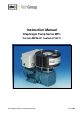
Instruction Manual Diaphragm Pump Series MP® Version MP26-H1 heated at 180°C Gas sampling and gas conditioning technology 6-1.1.
Dear customer, we have made up this operating manual in such a way that all necessary information about the product can be found and understood quickly and easily. Should you still have any question, please do not hesitate to contact M&C directly or go through your appointed dealer. Respective contact addresses are to be found in the annexe to this operating manual. Please also contact our homepage www.mc-techgroup.com for further information about our products.
Content 1 2 3 4 5 6 7 8 General information .................................................................................................................... 4 Declaration of conformity .......................................................................................................... 4 Safety instructions ...................................................................................................................... 5 Warranty ............................................................
Head Office M&C TechGroup Germany GmbH Rehhecke 79 40885 Ratingen Germany Telephone: 02102 / 935 - 0 Fax: 02102 / 935 - 111 E - mail: info@mc-techgroup.com www.mc-techgroup.com 1 GENERAL INFORMATION The product described in this operating manual has been examined before delivery and left our works in perfect condition related to safety regulations. In order to keep this condition and to guarantee a safe operation, it is important to heed the notes and prescriptions made in this operating manual.
3 SAFETY INSTRUCTIONS Please take care of the following basic safety procedures when mounting, starting up or operating this equipment: Read this operating manual before starting up and use of the equipment. The information and warnings given in this operating manual must be heeded. Any work on electrical equipment is only to be carried out by trained specialists as per the regulations currently in force.
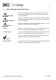
5 USED TERMS AND SIGNAL INDICATIONS DANGER! This means that death, severe physical injuries and/or important material damages will occur in case the respective safety measures are not fulfilled. WARNING! This means that death, severe physical injuries and/or important material damages may occur in case the respective safety measures are not fulfilled. This means that minor physical injuries may occur in case the respective safety measures are not fulfilled.
6 INTRODUCTION The electrically heated diaphragm pump MP26-H1 is suitable for corrosive hot wet gases. It is constructed especially for gas transportation in hot wet gas analysis systems . 7 DESCRIPTION All sample wetted parts of the pump MP26-H1 are made of PTFE. This makes the pump suitable for hot wet applications with corrosive gases. The pump works absolutely lubricant free. This means that the sample remains analytically unchanged.
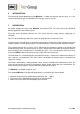
8 TECHNICAL DATA Diaphragm pump Part number Power supply Degree of protection Capacity max. Operating pressure Sample temperature Ambient temperature Storage temperature Gas connections Electrical standard Material of sample wetted parts Weight 8.1 MP26-H1.. 02P1300 230V,50Hz 02P1305 115V,60Hz IP 44 - DIN 40050 10,0 l/min without pressure 0,3 to 2,2 bar abs.
10 RECEIPT OF GOODS AND STORAGE Please take the sample pump and possible special accessories carefully out of the packaging material immediately after arrival, and compare the goods with the items listed on the delivery note! Check the goods for any damage caused during delivery and, if necessary, notify your transport insurance company without delay of any damage discovered. The equipment should be stored in a protected, frost-free room.
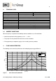
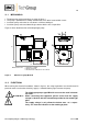
11.1 MECHANICAL The dimensions of the mountings are given in figure 1 The pump is provided for assembly and therefore it has to be fastened with screws. Install the pump so that the fan can draw in sufficient cooling air. Install the pump so that accidental finger contact with the fan is impossible. Figure 2 shows the dimensions of the diaphragm pump. G1/4" 34 3 1 2 250 ø6 71 ø11 60 300 Dimension in mm Figure 2 11.
Take care that safety regulations are observed when connecting the pump to the power supply. NOTE! Attention must be paid to the requirements of IEC 364 (DIN VDE 0100) when setting high-power electrical units with nominal voltages of up to 1000 V, together with the associated standards and stipulations. Check the details on the type plate to ensure that the equipment is connected up to the correct mains voltage. A main switch and matching fuse must be provided externally (EN 60335-1).
11.3 PNEUMATIC Components connected to the pump must be designed according to the pneumatic performance of the pump (see technical data). NOTE! The pump must only be used in the conditions specified in the technical data. Remove the protection plugs from the port threads (thread size G1/4”). Accessories like temperature resistant hose connections are screwed into the port threads by sealing tape. Connect the suction and pressure heated lines. 12 SUPPLY LINE CONNECTIONS 12.
13 START-UP Specific safety instructions for media being handled must be observed. Before pumping a medium, the compatibility of materials of pump head, diaphragm and valves with the medium must be checked (for pump materials: see technical data). The following steps should be carried out before initial start-up: The pump must not start against pressure or vacuum. When it is switched on the pressure in the suction and pressure lines must be atmospheric.
15 MAINTENANCE Before the maintenance work is carried out, it is necessary that the specific safety procedures pertaining to the system and operational process be observed! WARNING! It is necessary to take the pump off the mains before any assembly, maintenance or repair work is carried out! Wait until the temperature is low enough to do maintenance. Diaphragm and valve plates are the only parts of the pump subject to wear. They are simple to change. WARNING! Aggressive medium is possible.
Parts and tools required: Valve plates, sealing rings (2 each pump head) and structured diaphragm(s) Screwdriver no. 1 Always change valve plates, diaphragm and sealing rings at the same time. NOTE! Change the diaphragm, valve plates and sealing rings in the following sequence: 15.1 REMOVING THE DIAPHRAGM AND VALVE PLATES Before removing the valve plates or the diaphragm the heater assembly must be removed from the pump head.
15.2 CLEANING When changing valve plates and diaphragm, inspect all parts for dirt before assembling the pump head and clean them if necessary. As far as possible clean the parts with a dry cloth. Solvents should not be used as they can attack the plastics and synthetic rubber parts. If a compressed air line is available, blow the parts out with it. WARNING! Aggressive medium is possible.
16 TROUBLE SHOOTING Before working on the pump isolate the power supply securely, then check that the lines are not live. The following tips for fault-finding are best employed in the sequence shown. Problem/indication Pump produces no flow Flow, pressure or vacuum too low NOTE! Possible cause Action/Check No main supply. Check power supply. Check plug for correct fit. Connections or lines are blocked. An external valve is closed or a filter is blocked.
17 SPARE PARTS LIST Wear, tear and replacement part requirements depend on specific operating conditions. The recommended quantities are based on experience and are not binding. Diaphragm sample pump Type MP26-H1 (C) consumable parts, (R) recommended spare parts, (S) spare parts Recommended quantity Being in operation [years] C/R/S C 1 1 2 2 3 3 90P5010 O-ring 25 C 1 2 3 90P5005 Valve plate1 pc., Material: PTFE (required 2 pc.) C 2 4 6 90P5025 Valve body type C/D 1/4”i, PTFE 1 pc.