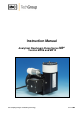
Instruction Manual Analytical Diaphragm Pump Series MP ® Version MP06 and MP12 Gas sampling and gas conditioning technology 6-1.1.
Dear customer, we have made up this operating manual in such a way that all necessary information about the product can be found and understood quickly and easily. Should you still have any question, please do not hesitate to contact M&C directly or go through your appointed dealer. Respective contact addresses are to be found in the annexe to this operating manual. Please also contact our homepage www.mc-techgroup.com for further information about our products.
List of Contents 1 General information...................................................................................................................... 4 2 Declaration of conformity ............................................................................................................ 4 3 Safety instructions ....................................................................................................................... 5 4 Warranty ........................................................
Head Office M&C TechGroup Germany GmbH Rehhecke 79 40885 Ratingen Germany Telephone: 02102 / 935 - 0 Fax: 02102 / 935 - 111 E - mail: info@mc-techgroup.com www.mc-techgroup.com 1 GENERAL INFORMATION The product described in this operating manual has been examined before delivery and left our works in perfect condition related to safety regulations. In order to keep this condition and to guarantee a safe operation, it is important to heed the notes and prescriptions made in this operating manual.
3 SAFETY INSTRUCTIONS Please take care of the following basic safety procedures when mounting, starting up or operating this equipment: Read this operating manual before starting up and use of the equipment. The information and warnings given in this operating manual must be heeded. Any work on electrical equipment is only to be carried out by trained specialists as per the regulations currently in force.
5 USED TERMS AND SIGNAL INDICATIONS DANGER! This means that death, severe physical injuries and/or important material damages will occur in case the respective safety measures are not fulfilled. WARNING! This means that death, severe physical injuries and/or important material damages may occur in case the respective safety measures are not fulfilled. This means that minor physical injuries may occur in case the respective safety measures are not fulfilled.
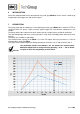
6 INTRODUCTION Due to the implementation of resistant materials the pump type MP06/12 can be used in a wide range of applications with aggressive and corrosive gases. 7 DESCRIPTION The pump head and all wetted parts of the diaphragm pumps type MP06/12 are made of PTFE respectively FKM. This grants a high resistance against aggressive and corrosive components in the sample. The pumps work 100% lubricant free which means that the sample remains analytical unaffected.
7.1 AMBIENT CONDITIONS During operation the following ambient conditions must be kept: Ambient temperature during operating: -10°C .... + 40°C. The pump must be protected against the effects of dust and water. During operating an adequate supply of air for cooling must be provided. 7.2 SAFETY The protection class of the pumps MP06/12 is IP54. In case a high content of water and/or dust loading in the ambience, measures have to be taken to protect the pump before starting-up.
9 RECEIPT OF GOODS AND STORAGE Please take the sample pump and possible special accessories carefully out of the packaging material immediately after arrival, and compare the goods with the items listed on the delivery note! Check the goods for any damage caused during delivery and, if necessary, notify your transport insurance company without delay of any damage discovered The equipment should be stored in a protected, frost-free room! NOTE! 10 INSTALLATION INSTRUCTIONS When installing the pump
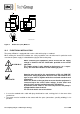
A 153 MP 06/12 Power in 230V 50Hz 52 124 50 55 165 4xM4 view A G1/8"i 24 Figure 2 10.2 Dimensions in mm Dimensions (mm) MP06/12 ELECTRICAL INSTALLATION The pumps MP06/12 is equipped with a mains cable with a plug as standard. When making the electrical installation the safety regulations must be observed. In particular make sure that the power supply is isolated before trying to connect the pump.
10.3 PNEUMATIC INSTALLATION Remove the protection plugs from the connection threads (thread size G1/8”i). Accessories like hose connections are screwed into the connection threads by sealing tape (using M&C connectors sealing tape is not necessary). Connect the suction and pressure lines. Arrange the suction and pressure lines so that condensate cannot run into the pump. The pump must only be used in the conditions specified in the technical data.
12 STARTING Specific safety instructions for media being handled must be observed. Before pumping a medium, the compatibility of materials of pump head, diaphragm and valves with the medium must be checked (for pump materials: see technical data). The following steps should be carried out before initial start-up: The pump must not start against pressure or vacuum. When it is switched on, the pressure in the suction and pressure lines must be atmospheric.
14 MAINTENANCE Before maintenance is carried out, it is necessary that the specific safety procedures pertaining to the system and operational process are observed! WARNING! It is necessary to take the pump off the mains before any assembly, maintenance or repair work is carried out! Diaphragm and valve plates are the only parts of the pump subject to wear. They are simple to change. WARNING! Aggressive medium is possible.
14.1 CHANGING THE DIAPHRAGM, VALVES AND SEALINGS Hexagon screws Figure 3 Pump head with hexagon screws Loosen the 4 hexagon screws; Remove the 2 parts of the pump head.
14.2 CLEANING When changing valve plates and diaphragm, inspect all parts for dirt before assembling the pump head and clean them if necessary. As far as possible clean the parts with a dry cloth. Solvents should not be used as they can attack the plastics and synthetic rubber parts. If possible clean the parts with compressed air. WARNING! Aggressive medium possible.
15 TROUBLE SHOOTING Before working on the pump, isolate the power supply securely, then check that the lines are not live. The following tips for fault-finding are best employed in the sequence shown. Problem/indication Possible cause Pump produces no No main supply. flow Flow, pressure or vacuum too low NOTE! Connections or lines are blocked. An external valve is closed or a filter is blocked. Liquid (condensate) has collected in the pump head. Diaphragm or valves are worn out.
16 SPARE PART LIST Wear, tear and replacement part requirements depend on specific operating conditions. The recommended quantities are based on experience and are not binding.